
Installation guide


Adjustments
VCO Bias Potentiometer Calibration
4-11
VCO Bias Potentiometer Calibration
Description
This adjustment sets the VCO bias potentiometer at a level that will keep the VCO in a stable operating
region over the entire frequency and temperature range. First, the F/2 and the lock angle potentiometers are
set fully CW (clock-wise). The signal generator is set to 750 MHz and the potentiometer is adjusted until the
F/2 oscillations disappear. The voltage at the SYNTH_F2 ABUS node is measured and then the potentiometer
is adjusted for a 0.77 V to 0.80 V drop.
After you have performed this adjustment, you must perform the “Lock Angle Potentiometer Calibration (Not
Used with Option UNJ or Option 506)” on page 4-12.
Required Test Equipment
• Agilent 8563EC Option 001 spectrum analyzer
Procedure
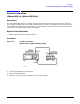
Figure 4-5 VCO Bias Potentiometer Calibration Setup
1. Connect the equipment as shown above.
2. Preset all of the equipment.
3. Follow the instructions as they appear on the controller’s display.