
User`s guide


Table Of Contents
- Agilent E3632A DC Power Supply
- Table of Contents
- List of Figures
- List of Tables
- 1 Getting Started
- 2 Operation and Features
- Overview
- Constant Voltage Operation
- Constant Current Operation
- Storing and Recalling Operating States
- Programming the Overvoltage Protection
- Programming the Overcurrent Protection
- Remote Voltage Sensing
- Disabling the Output
- System-Related Operations
- Remote Interface Configuration
- GPIB Interface Configuration
- RS-232 Interface Configuration
- Calibration
- 3 Remote Interface Reference
- SCPI Command Summary
- Introduction to the SCPI Language
- Simplified Programming Overview
- Using the APPLy Command
- Output Settings and Operation Commands
- Triggering Commands
- System-Related Commands
- Calibration Commands
- RS-232 Interface Commands
- SCPI Status Registers
- What is an event register?
- What is an enable register?
- SCPI status system
- The Questionable Status register
- The Standard Event register
- The Status Byte register
- Using Service Request (SRQ) and Serial POLL
- Using *STB? to read the Status Byte
- Using the Message Available Bit (MAV)
- To interrupt your bus controller using SRQ
- To determine when a command sequence is completed
- Using *OPC to signal when data is in the output buffer
- Status Reporting Commands
- Halting an Output in Progress
- SCPI Conformance Information
- IEEE-488 Conformance Information
- 4 Error Messages
- 5 Application Programs
- 6 Tutorial
- 7 Characteristics and Specifications
2 Operation and Features
RS-232 Interface Configuration
58 E3632A User’s Guide
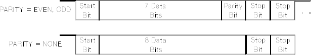
RS-232 data frame format
A character frame consists of all the transmitted bits that
make up a single character. The frame is defined as the
characters from the start bit to the last stop bit, inclusively.
Within the frame, you can select the baud rate, number of
data bits, and parity type. The power supply uses the
following frame formats for seven and eight data bits.
Figure 2-3 RS-232 data frame format
Connection to a computer or terminal
To connect the power supply to a computer or terminal, you
must have the proper interface cable. Most computers and
terminals are DTE (Data Terminal Equipment) devices. Since
the power supply is also a DTE device, you must use a
DTE- to- DTE interface cable. These cables are also called
null- modem, modem- eliminator, or crossover cables.
The interface cable must also have the proper connector on
each end and the internal wiring must be correct.
Connectors typically have nine pins (DB- 9 connector) or 25
pins (DB- 25 connector) with a “male” or “female” pin
configuration. A male connector has pins inside the
connector shell and a female connector has holes inside the
connector shell.
If you cannot find the correct cable for your configuration,
you may have to use a wiring adapter. If you are using a
DTE- to- DTE cable, make sure the adapter is a
“straight- through” type. Typical adapters include gender
changers, null- modem adapters, and DB- 9 to DB- 25
adapters.