
User`s guide


Table Of Contents
- Agilent E3632A DC Power Supply
- Table of Contents
- List of Figures
- List of Tables
- 1 Getting Started
- 2 Operation and Features
- Overview
- Constant Voltage Operation
- Constant Current Operation
- Storing and Recalling Operating States
- Programming the Overvoltage Protection
- Programming the Overcurrent Protection
- Remote Voltage Sensing
- Disabling the Output
- System-Related Operations
- Remote Interface Configuration
- GPIB Interface Configuration
- RS-232 Interface Configuration
- Calibration
- 3 Remote Interface Reference
- SCPI Command Summary
- Introduction to the SCPI Language
- Simplified Programming Overview
- Using the APPLy Command
- Output Settings and Operation Commands
- Triggering Commands
- System-Related Commands
- Calibration Commands
- RS-232 Interface Commands
- SCPI Status Registers
- What is an event register?
- What is an enable register?
- SCPI status system
- The Questionable Status register
- The Standard Event register
- The Status Byte register
- Using Service Request (SRQ) and Serial POLL
- Using *STB? to read the Status Byte
- Using the Message Available Bit (MAV)
- To interrupt your bus controller using SRQ
- To determine when a command sequence is completed
- Using *OPC to signal when data is in the output buffer
- Status Reporting Commands
- Halting an Output in Progress
- SCPI Conformance Information
- IEEE-488 Conformance Information
- 4 Error Messages
- 5 Application Programs
- 6 Tutorial
- 7 Characteristics and Specifications
2 Operation and Features
Programming the Overcurrent Protection
38 E3632A User’s Guide
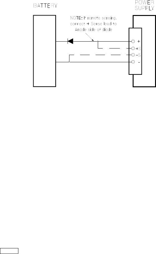
Figure 2-1 Recommended protection circuit for battery charging
Programming the Overcurrent Protection
Overcurrent protection guards the load against output
currents that reach a specified value greater than the
programmed protection level. It is accomplished by
programming the output current to zero.
The following steps show how to set the overcurrent
protection trip level, how to check OCP operation and how
to clear overcurrent condition.
Front panel operation
Setting the OCP level and enable the OCP circuit
1 Turn on the power supply.
The power supply will go into the power- on/reset state,
the output is disabled (the OFF annunciator turns on), the
15 V/7 A range is selected (the 15V annunciator turns on);
and the knob is selected for voltage control.
Power