
User`s guide


Table Of Contents
- Agilent E3632A DC Power Supply
- Table of Contents
- List of Figures
- List of Tables
- 1 Getting Started
- 2 Operation and Features
- Overview
- Constant Voltage Operation
- Constant Current Operation
- Storing and Recalling Operating States
- Programming the Overvoltage Protection
- Programming the Overcurrent Protection
- Remote Voltage Sensing
- Disabling the Output
- System-Related Operations
- Remote Interface Configuration
- GPIB Interface Configuration
- RS-232 Interface Configuration
- Calibration
- 3 Remote Interface Reference
- SCPI Command Summary
- Introduction to the SCPI Language
- Simplified Programming Overview
- Using the APPLy Command
- Output Settings and Operation Commands
- Triggering Commands
- System-Related Commands
- Calibration Commands
- RS-232 Interface Commands
- SCPI Status Registers
- What is an event register?
- What is an enable register?
- SCPI status system
- The Questionable Status register
- The Standard Event register
- The Status Byte register
- Using Service Request (SRQ) and Serial POLL
- Using *STB? to read the Status Byte
- Using the Message Available Bit (MAV)
- To interrupt your bus controller using SRQ
- To determine when a command sequence is completed
- Using *OPC to signal when data is in the output buffer
- Status Reporting Commands
- Halting an Output in Progress
- SCPI Conformance Information
- IEEE-488 Conformance Information
- 4 Error Messages
- 5 Application Programs
- 6 Tutorial
- 7 Characteristics and Specifications
1Getting Started
Product at a Glance
20 E3632A User’s Guide
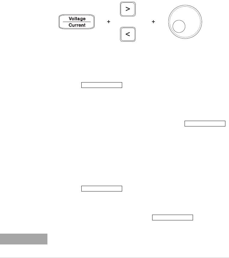
Voltage and current limit settings
You can set the voltage and current limit values from the
front panel using the following method.
Figure 1-3 Voltage and current limit settings
1 Select the desired range using the range selection keys
after turning on the power supply.
2 Press to show the limit values on the
display.
3 Move the blinking digit to the appropriate position using
the resolution selection keys and change the blinking digit
value to the desired voltage limit by turning the control
knob. If the display limit times out, press
again.
4 Set the knob to current control mode using the
voltage/current adjust selection key.
5 Move the blinking digit to the appropriate position using
the resolution selection keys and change the blinking digit
value to the desired current limit by turning the control
knob.
6 Press to enable the output. After about
five seconds, the display will go to output monitoring
mode automatically to display the voltage and current at
the output or the display will go to output monitoring
mode immediately by pressing
again.
Display Limit
Display Limit
Output On/Off
Display Limit
NOTE
All the front panel keys and controls can be disabled with the remote
interface commands. The power supply must be in the Local mode for the
front panel keys and controls to function.