User`s guide
Table Of Contents
- Agilent E3632A DC Power Supply
- Table of Contents
- List of Figures
- List of Tables
- 1 Getting Started
- 2 Operation and Features
- Overview
- Constant Voltage Operation
- Constant Current Operation
- Storing and Recalling Operating States
- Programming the Overvoltage Protection
- Programming the Overcurrent Protection
- Remote Voltage Sensing
- Disabling the Output
- System-Related Operations
- Remote Interface Configuration
- GPIB Interface Configuration
- RS-232 Interface Configuration
- Calibration
- 3 Remote Interface Reference
- SCPI Command Summary
- Introduction to the SCPI Language
- Simplified Programming Overview
- Using the APPLy Command
- Output Settings and Operation Commands
- Triggering Commands
- System-Related Commands
- Calibration Commands
- RS-232 Interface Commands
- SCPI Status Registers
- What is an event register?
- What is an enable register?
- SCPI status system
- The Questionable Status register
- The Standard Event register
- The Status Byte register
- Using Service Request (SRQ) and Serial POLL
- Using *STB? to read the Status Byte
- Using the Message Available Bit (MAV)
- To interrupt your bus controller using SRQ
- To determine when a command sequence is completed
- Using *OPC to signal when data is in the output buffer
- Status Reporting Commands
- Halting an Output in Progress
- SCPI Conformance Information
- IEEE-488 Conformance Information
- 4 Error Messages
- 5 Application Programs
- 6 Tutorial
- 7 Characteristics and Specifications

Characteristics and Specifications 7
Supplemental Characteristics
E3632A User’s Guide 171
Supplemental Characteristics
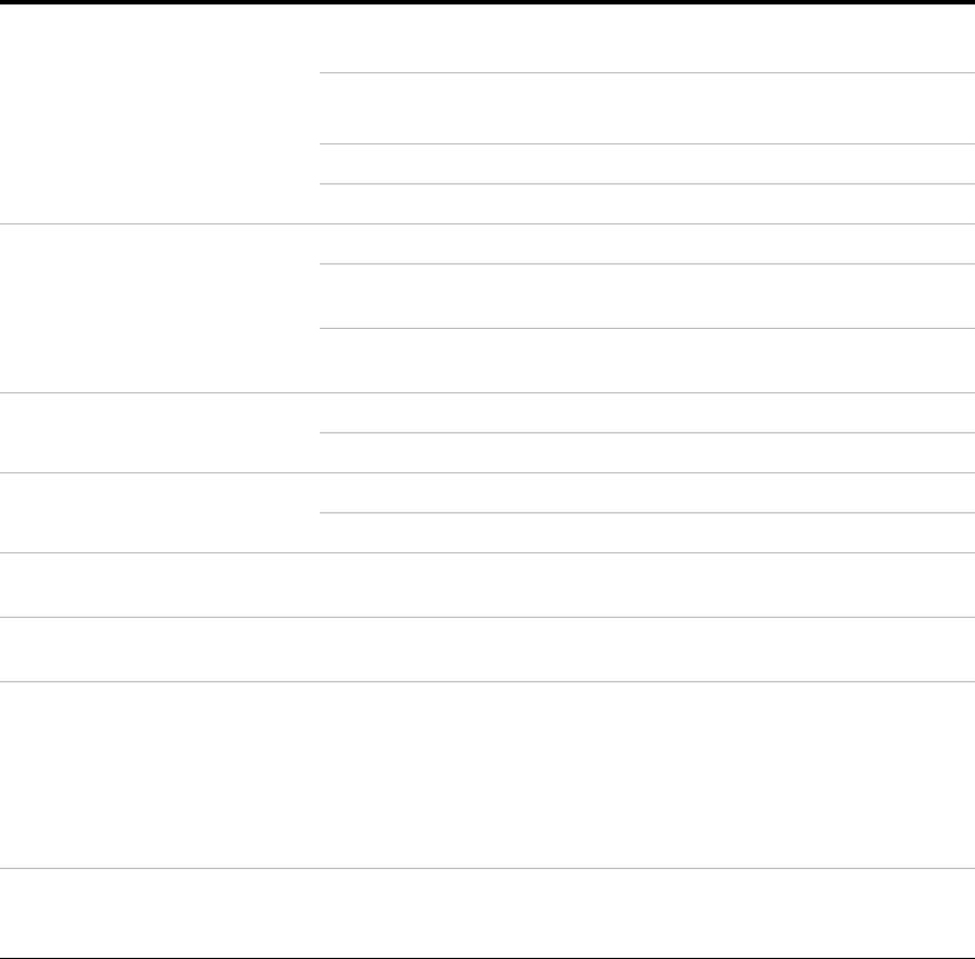
Table 7 - 3 Supplemental characteristics
Output programming range
(maximum programmable values)
Low range 0 V to 15.45 V
0 V to 7.21 A
High range 0 V to +20.6 V
0 V to 1.545 A
OVP 1 V to 32 V
OCP 0 A to 7.5 A
Remote sensing capability Voltage drop Up to 1 V per each lead
Load regulation Add 5 mV to specification for each 1 V change in the + output
lead due to load current changes.
Load voltage Subtract the voltage drop in the load leads from the specified
output voltage rating.
Temperature coefficient
[1]
±(% of output + offset)
Voltage <0.01% + 3 mV
Current <0.02% + 3 mA
Stability
[2]
±(% of output + offset)
Voltage <0.02% + 1 mV
Current <0.1% + 1 mA
Voltage programming speed
[3]
Up • 50 ms (full load)
• 20 ms (no load)
Down • 45 ms (full load)
• 400 ms (no load)
Output terminal isolation
(maximum, from chassis ground)
• ±60 Vdc when connecting shorting conductors without
insulation between the (+) output and the (+) sense
terminals and between the (–) output and the (–) sense
terminals.
• ±240 Vdc when connecting insulated shorting conductors
between the (+) output and the (+) sense terminals and
between the (–) output and the (–) sense terminals.
AC input ratings
(selectable via rear panel selector)
• 115 Vac ±10%, 47 Hz to 63 Hz (standard)
• 230 Vac ±10%. 47 Hz to 63 Hz (option 0E3)
• 100 Vac ±10%, 47 Hz to 63 Hz (option 0E9)


