
User`s guide


Table Of Contents
- Agilent E3632A DC Power Supply
- Table of Contents
- List of Figures
- List of Tables
- 1 Getting Started
- 2 Operation and Features
- Overview
- Constant Voltage Operation
- Constant Current Operation
- Storing and Recalling Operating States
- Programming the Overvoltage Protection
- Programming the Overcurrent Protection
- Remote Voltage Sensing
- Disabling the Output
- System-Related Operations
- Remote Interface Configuration
- GPIB Interface Configuration
- RS-232 Interface Configuration
- Calibration
- 3 Remote Interface Reference
- SCPI Command Summary
- Introduction to the SCPI Language
- Simplified Programming Overview
- Using the APPLy Command
- Output Settings and Operation Commands
- Triggering Commands
- System-Related Commands
- Calibration Commands
- RS-232 Interface Commands
- SCPI Status Registers
- What is an event register?
- What is an enable register?
- SCPI status system
- The Questionable Status register
- The Standard Event register
- The Status Byte register
- Using Service Request (SRQ) and Serial POLL
- Using *STB? to read the Status Byte
- Using the Message Available Bit (MAV)
- To interrupt your bus controller using SRQ
- To determine when a command sequence is completed
- Using *OPC to signal when data is in the output buffer
- Status Reporting Commands
- Halting an Output in Progress
- SCPI Conformance Information
- IEEE-488 Conformance Information
- 4 Error Messages
- 5 Application Programs
- 6 Tutorial
- 7 Characteristics and Specifications
Tutorial 6
Remote Programming
E3632A User’s Guide 165
When this exponential rise reaches the newly programmed
voltage level, the constant voltage amplifier resumes its
normal regulating action and holds the output constant.
Thus, the rise time can be determined approximately using
the formula shown in Figure 6- 8.
If no load resistor is attached to the power supply output
terminal, then the output voltage will rise linearly at a rate
of C
O
/I
L
when programmed upward, and
T
R
= C
O
(E
2
– E
1
)/I
L
, the shortest possible up- programming
time.
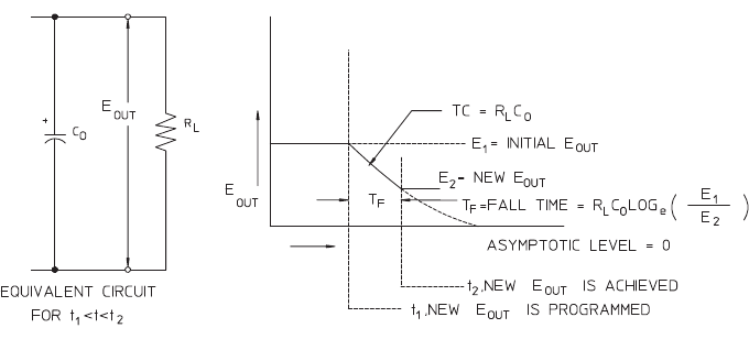
Figure 6-9 Speed of response — programming down
Figure 6- 9 shows that when the power supply is
programmed down, the regulator senses that the output
voltage is higher than desired and turns off the series
transistors entirely. Since the control circuit can in no way
cause the series regulator transistors to conduct backwards,
the output capacitor can only be discharged through the load
resistor and internal current source (I
S
).
The output voltage decays linearly with slope of I
S
/C
O
with
no load and stops falling when it reaches the new output
voltage which has been demanded. If full load is connected,
the output voltage will fall exponentially faster.