User’s Guide Part Number: E3632-90001 October 2007. For Safety information, Warranties, and Regulatory information, see the pages behind the Index. © Copyright Agilent Technologies, Inc. 2000-2007 All Rights Reserved.
The Agilent E3632A is a high performance 120 watt-dual range DC power supply with GPIB and RS-232 interfaces. The combination of bench-top and system features in this power supply provides versatile solutions for your design and test requirements.
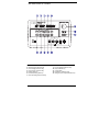
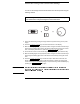
The Front Panel at a Glance 1 2 3 4 5 6 7 2 15V/7A range selection key 30V/4A range selection key Overvoltage protection key Overcurrent protection key Display limit key Recall operating state key Store operating state/Local key 8 9 10 11 12 13 Error/Calibrate key I/O Configuration/Secure key Output On/Off key Control knob Resolution selection keys Voltage/current adjust selection key
1 15V/7A range selection key Selects the 15V/7A range and allows the full rated output to 15V/7A. 2 30V/4A range selection key Selects the 30V/4A range and allows the full rated output to 30V/4A. 3 Overvoltage protection key Enables or disables the overvoltage protection function, sets trip voltage level, and clears the overvoltage condition. 4 Overcurrent protection key Enables or disables the overcurrent protection function, sets trip current level, and clears the overcurrent condition.
Front-Panel Voltage and Current Limit Settings You can set the voltage and current limit values from the front panel using the following method. Use the voltage/current adjust selection key, the resolution selection keys, and the control knob to change the voltage and current limit values. 1 Select the desired range using the range selection keys after turning on the power supply. 2 Press the Display Limit key to show the limit values on the display.
Display Annunciators Adrs Rmt 15V 30V OVP OCP CAL Limit ERROR OFF Unreg CV CC Power supply is addressed to listen or talk over a remote interface. Power supply is in remote interface mode. Shows the 15V/7A range is selected. Shows the 30V/4A range is selected. The overvoltage protection function is enabled when the annunciator turns on or the overvoltage protection circuit has caused the power supply to shutdown when the annunciator blinks.
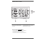
The Rear Panel at a Glance 1 Power-line voltage setting 2 Power-line fuse-holder assembly 3 AC inlet 4 Power-line module 5 GPIB (IEEE-488) interface connector 6 RS-232 interface connector Use the front-panel I/O Config key to: • • • 6 Select the GPIB or RS-232 interface (see chapter 3). Set the GPIB bus address (see chapter 3). Set the RS-232 baud rate and parity (see chapter 3).
In This Book General Information Chapter 1 contains a general description of your power supply. This chapter also provides instructions for checking your power supply, connecting to ac power, and selecting power-line voltage. Initial Operation Chapter 2 ensures that the power supply develops its rated outputs and properly responds to operation from the front panel.
8
Contents Chapter 1 General Information Safety Considerations 14 Safety and EMC Requirements 14 Options and Accessories 15 Options 15 Accessories 15 Description 16 Installation 19 Initial Inspection 19 Cooling and Location 19 Input Power Requirements 22 Power-Line Cord 22 Power-Line Voltage Selection 22 Contents Chapter 2 Initial Operation Preliminary Checkout 27 Power-On Checkout 28 Output Checkout 29 Voltage Output Checkout 29 Current Output Checkout 30 Chapter 3 Front-Panel Operation Front-Panel Op
Contents Chapter 3 Front-Panel Operation (continued) Contents Disabling the Output 50 Disabling the Output Using an External Relay 51 Knob Locking 51 System-Related Operations 52 Self-Test 52 Error Conditions 53 Display Control 54 Firmware Revision Query 55 SCPI Language Version 55 Remote Interface Configuration 56 Remote Interface Selection 56 GPIB Address 57 Baud Rate Selection (RS-232) 57 Parity Selection (RS-232) 57 To Set the GPIB Address 58 To Set the Baud Rate and Parity (RS-232) 59 GPIB Interface
Contents Chapter 4 Remote Interface Reference Contents SCPI Command Summary 73 Simplified Programming Overview 78 Using the APPLy Command 78 Using the Low-Level Commands 78 Reading a Query Response 79 Selecting a Trigger Source 79 Power Supply Programming Ranges 80 Using the APPLy Command 81 Output Setting and Operation Commands 82 Triggering Commands 89 Trigger Source Choices 89 Triggering Commands 91 System-Related Commands 92 Calibration Commands 96 RS-232 Interface Commands 99 The SCPI Status Registe
Contents Chapter 5 Error Messages Execution Errors 123 Self-Test Errors 128 Calibration Errors 129 Chapter 6 Application Programs C++ Example for GPIB(IEEE 488) 133 Excel 5.0 Example for Windows 3.
1 General Information
General Information This chapter provides a general description of your power supply. This chapter also contains instructions for initial inspection, location and cooling for bench and rack operation, selecting the power-line voltage, and connecting your power supply to ac power. Safety Considerations This power supply is a Safety Class I instrument, which means that it has a protective earth terminal. That terminal must be connected to earth ground through a power source with a 3-wire ground receptacle.
Chapter 1 General Information Options and Accessories 1 Options and Accessories Options Options 0EM, 0E3, and 0E9 determine which power-line voltage is selected at the factory. The standard unit is configured for 115 Vac ± 10%, 47-63 Hz input voltage. For more information about changing the power-line voltage setting, see ‘‘Power-Line Voltage Selection’’, starting on page 22 in this chapter.
Chapter 1 General Information Description Description The Agilent E3632A DC power supply feature a combination of programming capabilities and linear power supply performance that makes it ideal for power systems applications. The power supply is programmable locally from the front panel or remotely over the GPIB and RS-232 interfaces. This power supply has two ranges, allowing more voltage at a lower current. The desired output range is selected from the front panel or over the remote interfaces.
Chapter 1 General Information Description 1 When operated over the remote interface, the power supply can be both a listener and a talker. Using an external controller, you can instruct the power supply to set the output and to send the status data back over the GPIB or RS232.
Chapter 1 General Information Description Warning Outputs can be floated to maximum of ±240 Vdc provided that the metal shorting bars without insulation are either replaced with insulated conductors or they are removed from the terminals so there is no operator access to the output conductors without insulation. All field wiring insulation must be adequate for the voltage present. The power supply is shipped with a detachable, 3-wire grounding type power cord.
Chapter 1 General Information Installation 1 Installation Initial Inspection When you receive your power supply, inspect it for any obvious damage that may have occurred during shipment. If any damage is found, notify the carrier and the nearest Agilent Sales Office immediately. Warranty information is shown in the front of this manual. Keep the original packing materials in case the power supply has to be returned to Agilent Technologies in the future.
Chapter 1 General Information Installation Rack Mounting The power supply can be mounted in a standard 19-inch rack cabinet using one of three optional kits available. A rack-mounting kit for a single instrument is available as Option 1CM (P/N 5063-9243). Installation instructions and hardware are included with each rack-mounting kit. Any Agilent System II instrument of the same size can be rack-mounted beside the Agilent E3632A power supply.
Chapter 1 General Information Installation 1 To rack mount two instrument of the same depth side-by-side, order lock-link kit 5061-9694 and flange kit 5063-9214. To install two instruments in a sliding support shelf, order support shelf 5063-9256, and slide kit 1494-0015.
Chapter 1 General Information Input Power Requirements Input Power Requirements You can operate your power supply from a nominal 100 V, 115 V, or 230 V single phase ac power source at 47 to 63 Hz. An indication on the rear panel shows the nominal input voltage set for the power supply at the factory. If necessary, you can change the power-line voltage setting according to the instructions on the next page.
Chapter 1 General Information Input Power Requirements 1 1 Remove the power cord. Remove the fuse-holder assembly with a flat-blad screwdriver from the rear panel. 2 Install the correct line fuse. Remove the power-line voltage selector from the power-line module. 100 or 115 Vac, 4 AT fuse 230 Vac, 2.5 AT fuse 3 Rotate the power-line voltage selector until the correct voltage appears. 4 Replace the power-line voltage selector and the fuse-holder assembly in the rear panel.
Chapter 1 General Information Input Power Requirements 24
Chapter 1 General Information Input Power Requirements 1 25
2 Initial Operation
Initial Operation There are three basic tests in this chapter. The automatic power-on test includes a self-test that checks the internal microprocessors and allows the user visually to check the display. The output check ensures that the power supply develops its rated outputs and properly responds to operation from the front panel. For complete performance and/or verification tests, refer to the Service Guide.
Chapter 2 Initial Operation Preliminary Checkout Preliminary Checkout 1 2 3 The following steps help you verify that the power supply is ready for use. Verify the power-line voltage setting on the rear panel. The power-line voltage is set to the proper value for your country when the power supply is shipped from the factory. Change the voltage setting if it is not correct. The settings are: 100, 115, or 230 Vac. Verify that the correct power-line fuse is installed.
Chapter 2 Initial Operation Power-On Checkout Power-On Checkout The power-on test includes an automatic self-test that checks the internal microprocessors and allows the user visually to check the display. You will observe the following sequence on the display after pressing the front panel power switch to on. 1 All segments of the display including all annunciators will turn on for about one second. To review the annunciators, hold down the power supply.
Chapter 2 Initial Operation Output Checkout Output Checkout The following procedures check to ensure that the power supply develops its rated outputs and properly responds to operation from the front panel. For complete performance and verification tests, refer to the Service Guide. For each step, use the keys shown on the left margins. Voltage Output Checkout The following steps verify basic voltage functions with no load. Power 1 Turn on the power supply.
Chapter 2 Initial Operation Output Checkout Current Output Checkout The following steps check basic current functions with a short across the power supply’s output. Power 1 2 Output On/Off Display Limit Volt/Curr Turn on the power supply. The power supply will go into the power-on / reset state; the output is disabled (the OFF annunciator turns on); the 15V/7A range is selected (the 15V annunciator turns on); and the knob is selected for voltage control.
Chapter 2 Initial Operation Output Checkout 6 Note Ensure that the current can be adjusted from zero to the full rated value. Adjust the knob until the ammeter indicates 0 amps and then until the ammeter indicates 7.0 amps. 1 If an error has been detected during the output checkout procedures, the ERROR annunciator will turn on. See "Error Messages" for more information starting on page 121 in chapter 5.
Chapter 2 Initial Operation Output Checkout 32
3 Front-Panel Operation
Front-Panel Operation So far you have learned how to install your power supply and perform initial operation. During the initial operation, you were briefly introduced to operating from the front panel as you learned how to check basic voltage and current functions. This chapter will describe in detail the use of these frontpanel keys and show how they are used to accomplish power supply operation.
Chapter 3 Front-Panel Operation Front-Panel Operation Overview Front-Panel Operation Overview The following section describes an overview of the front-panel keys before operating your power supply. • The power supply is shipped from the factory configured in the front-panel operation mode. At power-on, the power supply is automatically set to operate in the front-panel operation mode. When in this mode, the frontpanel keys can be used.
Chapter 3 Front-Panel Operation Constant Voltage Operation Constant Voltage Operation To set up the power supply for constant voltage (CV) operation, proceed as follows. • Front-panel operation: 1 Connect a load to the output terminals. With power-off, connect a load to the (+) and (-) output terminals. Power Display Limit 2 Turn on the power supply.
Chapter 3 Front-Panel Operation Constant Voltage Operation Volt/Curr Display Limit Output On/Off 5 Adjust the knob for the desired output voltage. 1 Check that the Limit annunciator still blinks. Set the knob for voltage control. The second digit of the voltmeter will be blinking. Change the blinking digit using the resolution selection keys and adjust the knob to the desired output voltage. 6 Return to the meter mode.
Chapter 3 Front-Panel Operation Constant Current Operation Constant Current Operation To set up the power supply for constant current (CC) operation, proceed as follows. • Front-panel operation: 1 Connect a load to the output terminals. With power-off, connect a load to the (+) and (-) output terminals. Power Display Limit 2 Turn on the power supply.
Chapter 3 Front-Panel Operation Constant Current Operation Volt/Curr Display Limit Output On/Off 5 Adjust the knob for the desired output current. 1 Check that the Limit annunciator still blinks. Set the knob for current control. The second digit of the ammeter will be blinking. Change the blinking digit using the resolution selection keys and adjust the knob to the desired output current. 6 Return to the meter mode.
Chapter 3 Front-Panel Operation Storing and Recalling Operating States Storing and Recalling Operating States You can store up to three different operating states in non-volatile memory. This also enables you to recall the entire instrument configuration with just a few key presses from the front panel. The memory locations are supplied with the reset states from the factory for front-panel operation. Refer to the description of *RST command, starting on page 94 in chapter 4 for more information.
Chapter 3 Front-Panel Operation Storing and Recalling Operating States Store 4 Save the operating state. The operating state is now stored. To recall the stored state, go to the following steps. DONE This message appears on the display for approximately 1 second. Recall 5 Turn on the recall mode. Memory location “1” will be displayed in the recall mode. 3 RECALL 1 6 This message appears on the display for approximately 3 seconds. Recall the stored operating state.
Chapter 3 Front-Panel Operation Programming Overvoltage Protection Programming Overvoltage Protection Overvoltage protection guards the load against output voltages that reach a specified value greater than the programmed protection level. It is accomplished by shorting the output via an internal SCR when the trip level is set to equal or greater than 3 volts, or by progamming the output to 1 volt when the trip level is set to less than 3 volts.
Chapter 3 Front-Panel Operation Programming Overvoltage Protection Over Voltage 5 Exit the OVP menu. CHANGED The “CHANGED” message is highlighted for a second to show that the new OVP trip level is now in effect. If the OVP settings are not changed, “NO CHANGE” will be displayed. The power supply will exit the OVP menu and the display will return to the meter mode. Check that the OVP annunciator turns on. Checking OVP Operation To check OVP operation, raise the output voltage to near the trip point.
Chapter 3 Front-Panel Operation Programming Overvoltage Protection Over Voltage Clear the overvoltage condition and exit this menu. Now, when you press Over Voltage key again, the “DONE” message is displayed for a second and the OVP annunciator will not blink any more. The output will return to meter mode.
Chapter 3 Front-Panel Operation Programming Overcurrent Protection Programming Overcurrent Protection Overcurrent protection guards the load against output currents that reach a specified value greater than the programmed protection level. It is accomplished by programming the output current to zero. The following steps show how to set the overcurrent protection trip level, how to check OCP operation and how to clear overcurrent condition.
Chapter 3 Front-Panel Operation Programming Overcurrent Protection Over Current 5 Exit the OCP menu. CHANGED The “CHANGED” message is displayed for a second to show that the new OCP trip level is now in effect. If the OCP settings are not changed, “NO CHANGE” will be displayed. The power supply will exit the OCP menu and the display will return to the meter mode. Check that the OCP annunciator turns on. Checking OCP Operation To check OCP operation, raise the output current to near the trip point.
Chapter 3 Front-Panel Operation Programming Overcurrent Protection Over Current Clear the overcurrent condition and exit this menu. Now, when you press Over Current key again, the “DONE’’ message is displayed for a second and the OCP annunciator will not blink any more. The output will return to meter mode.
Chapter 3 Front-Panel Operation Remote Voltage Sensing Remote Voltage Sensing Remote voltage sensing is used to maintain regulation at the load and reduce the degradation of regulation that would occur due to the voltage drop in the leads between the power supply and the load. By connecting the power supply for remote voltage sensing, voltage is sensed at the load rather than at the power supply’s output terminals.
Chapter 3 Front-Panel Operation Remote Voltage Sensing Stability Using remote sensing under certain combinations of load lead lengths and large load capacitances may cause your application to form a filter, which becomes part of the voltage feedback loop. The extra phase shift created by this filter can degrade the power supply’s stability, resulting in poor transient response or loop instability. In severe cases, it may cause oscillations.
Chapter 3 Front-Panel Operation Disabling the Output Disabling the Output The output of the power supply can be disabled or enabled from the front panel. • When the power supply is in the “Off” state, the OFF annunciator turns on and the output is disabled. The OFF annunciator turns off when the power supply returns to the “On” state. When the output is disabled, the voltage value is 0 volts and the current value is 0.02 amps.
Chapter 3 Front-Panel Operation Disabling the Output Using an External Relay Disabling the Output Using an External Relay When the output of the E3632A is turned off, it is implemented by setting the output to 0 volts and 0.02 amps. This gives a zero output voltage without actually disconnecting the output. To disconnect the output an external relay must be connected between the output and the load. A TTL signal of either low true or high true is provided to control an external relay.
Chapter 3 Front-Panel Operation System-Related Operations System-Related Operations This section gives information on topics such as self-test, error conditions, and front-panel display control. This information is not directly related to setting up the power supply but is an important part of operating the power supply. Self-Test A power-on self-test occurs automatically when you turn on the power supply. This test assures you that the power supply is operational.
Chapter 3 Front-Panel Operation System-Related Operations Error Conditions When the front-panel ERROR annunciator turns on, one or more command syntax or hardware errors have been detected. A record of up to 20 errors can be stored in the power supply’s error queue. See chapter 5 “Error Messages”, starting on page 121 for a complete listing of the errors. • Errors are retrieved in first-in-first-out (FIFO) order. The first error returned is the first error that was stored.
Chapter 3 Front-Panel Operation System-Related Operations Display Control For security reasons, you may want to turn off the front-panel display. From the remote interface, you can display a 12-character message on the front panel. The display can be enabled / disabled from the remote interface only. • When the display is turned off, outputs are not sent to the display and all annunciators are disabled except the ERROR annunciator.
Chapter 3 Front-Panel Operation System-Related Operations Firmware Revision Query The power supply has three microprocessors for control of various internal systems. You can query the power supply to determine which revision of firmware is installed for each microprocessor. You can query the firmware revision from the remote interface only. • The power supply returns four fields separated by commas and the fourth field is a revision code which contains three numbers.
Chapter 3 Front-Panel Operation Remote Interface Configuration Remote Interface Configuration Before you can operate the power supply over the remote interface, you must configure the power supply for the remote interface. This section gives information on configuring the remote interface. For additional information on programming the power supply over the remote interface, See "Remote Interface Reference", starting on page 71 in chapter 4.
Chapter 3 Front-Panel Operation Remote Interface Configuration GPIB Address Each device on the GPIB (IEEE-488) interface must have a unique address. You can set the power supply’s address to any value between 0 and 30. The current address is displayed momentarily on the front panel when you turn on the power supply. The address is set to “05” when the power supply is shipped from the factory. The GPIB address can be set from the front-panel only.
Chapter 3 Front-Panel Operation Remote Interface Configuration To Set the GPIB Address To configure the power supply for the GPIB interface, proceed as follows: I/O Config 1 Turn on the remote configuration mode. GPIB / 488 You will see the above message on the front-panel display if the power supply has not been changed from the factory setting. If “RS-232” appears, choose “GPIB / 488” by turning the knob to the right. I/O Config 2 Move to the GPIB address setting mode.
Chapter 3 Front-Panel Operation Remote Interface Configuration To Set the Baud Rate and Parity (RS-232) To configure the power supply for the RS-232 interface, proceed as follows: I/O Config 1 Turn on the remote configuration mode. GPIB / 488 You will see the above message on the display if the power supply has not been changed from the factory setting. 2 Notice that if you changed the remote interface selection to RS-232 before, “RS-232” message will be displayed. Choose the RS-232 interface.
Chapter 3 Front-Panel Operation Remote Interface Configuration I/O Config 5 Save the change and turn off the I/O configuration mode. CHANGE SAVED The RS-232 baud rate and parity selections are stored in non-volatile memory, and does not change when power has been off or after a remote interface reset. The power supply displays a message to show that the change is now in effect. If the baud rate and the parity are not changed, “NO CHANGE” will be displayed for one second.
Chapter 3 Front-Panel Operation GPIB Interface Configuration GPIB Interface Configuration The GPIB connector on the rear panel connects your power supply to the computer and other GPIB devices. Chapter 1 lists the cables that are available from Agilent Technologies. An GPIB system can be connected together in any configuration (star, linear, or both) as long as the following rules are observed: • The total number of devices including the computer is no more than 15.
Chapter 3 Front-Panel Operation RS-232 Interface Configuration RS-232 Interface Configuration You connect the power supply to the RS-232 interface using the 9-pin (DB-9) serial connector on the rear panel. The power supply is configured as a DTE (Data Terminal Equipment) device. For all communications over the RS-232 interface, the power supply uses two handshake lines: DTR (Data Terminal Ready, on pin 4) and DSR (Data Set Ready, on pin 6).
Chapter 3 Front-Panel Operation RS-232 Interface Configuration Connection to a Computer or Terminal To connect the power supply to a computer or terminal, you must have the proper interface cable. Most computers and terminals are DTE (Data Terminal Equipment) devices. Since the power supply is also a DTE device, you must use a DTE-to-DTE interface cable. These cables are also called null-modem, modem-eliminator, or crossover cables.
Chapter 3 Front-Panel Operation RS-232 Interface Configuration DB-25 Serial Connection If your computer or terminal has a 25-pin serial port with a male connector, use the null-modem cable and 25-pin adapter included with the Agilent 34398A Cable Kit. The cable and adapter pin diagram are shown below.
Chapter 3 Front-Panel Operation RS-232 Interface Configuration 2 When the power supply wants to “talk” over the interface (which means that it has processed a query) and has received a message terminator, it will set the DTR line FALSE. This implies that once a query has been sent to the power supply, the bus controller should read the response before attempting to send more data. It also means that a must terminate the command string.
Chapter 3 Front-Panel Operation Calibration Overview Calibration Overview This section gives an overview of the calibration features of the power supply. For more detailed discussion of the calibration procedures, see the Service Guide. Calibration Security This feature allows you to enter a security code to prevent accidental or unauthorized calibrations of the power supply. When you first receive your power supply, it is secured.
Chapter 3 Front-Panel Operation Calibration Overview To Unsecure for Calibration You can unsecure the power supply for calibration either from the front panel or over the remote interface. The power supply is secured when shipped from the factory, and the security code is set to “HP003632”. • Front-Panel Operation: SECURED If the power supply is secured, you will see the above message for one second by holding the Calibrate key for 5 seconds when you turn on the power supply.
Chapter 3 Front-Panel Operation Calibration Overview To Secure Against Calibration You can secure the power supply against calibration either from the front panel or over the remote interface. The power supply is secured when shipped from the factory, and the security code is set to “HP003632”. Be sure to read the security code rules on page 66 before attempting to secure the power supply.
Chapter 3 Front-Panel Operation Calibration Overview To Change the Security Code To change the security code, you must first unsecure the power supply, and then enter a new code. Be sure to read the security code rules on page 66 before attempting to secure the power supply. • Front-Panel Operation: To change the security code, first make sure that the power supply is unsecured.
Chapter 3 Front-Panel Operation Calibration Overview Calibration Count You can determine the number of times that your power supply has been calibrated. Your power supply was calibrated before it left the factory. When you receive your power supply, read the count to determine its initial value. The calibration count feature can be performed from the remote interface only.
Chapter 3 Front-Panel Operation Calibration Overview 3 71
4 Remote Interface Reference
Remote Interface Reference SCPI SCPI SCPI • • • • • • • • • • • • • • SCPI Command Summary, page 73 Simplified Programming Overview, page 78 Using the APPLy Command, page 81 Output Setting and Operation Commands, page 82 Triggering Commands, page 89 System-Related Commands, page 92 Calibration Commands, page 96 RS-232 Interface Commands, page 99 The SCPI Status Registers, page 100 Status Reporting Commands, page 108 An Introduction to the SCPI Language, page 111 Halting an Output in Progress, page 116
Chapter 4 Remote Interface Reference SCPI Command Summary SCPI Command Summary This section summarizes the SCPI (Standard Commands for Programmable Instruments) commands available to program the power supply over the remote interface. Refer to the later sections in this chapter for more complete details on each command. Throughout this manual, the following conventions are used for SCPI command syntax. • Square brackets ([ ]) indicate optional keywords or parameters.
Chapter 4 Remote Interface Reference SCPI Command Summary Output Setting and Measurement Commands APPLy {|DEF|MIN|MAX}[,{|DEF|MIN|MAX}] APPLy? [SOURce:] CURRent[:LEVel][:IMMediate][:AMPLitude]{|MIN|MAX|UP|DOWN} CURRent[:LEVel][:IMMediate][:AMPLitude]? [MIN|MAX] CURRent[:LEVel][:IMMediate]:STEP[:INCRement] { |DEFault} CURRent[:LEVel][:IMMediate]:STEP[:INCRement]? {DEFault} CURRent[:LEVel]:TRIGgered[:AMPLitude] {|MIN|MAX} CURRent[:LEVel]:TRIGgered[:AMPLitude
Chapter 4 Remote Interface Reference SCPI Command Summary Triggering Commands INITiate[:IMMediate] TRIGger[:SEQuence] :DELay {|MIN|MAX} :DELay? :SOURce {BUS|IMM} :SOURce? *TRG System-Related Commands DISPlay[:WINDow] [:STATe] {OFF|ON} [:STATe]? :TEXT[:DATA] :TEXT[:DATA]? :TEXT:CLEar SYSTem :BEEPer[:IMMediate] :ERRor? :VERSion? OUTPut :RELay[:STATe] {OFF|ON} :RELay[:STATe]? [:STATe] {OFF|ON} [:STATe]? 4 *IDN? *RST *TST? *SAV {1|2|3} *RCL {1|2|3} 75
Chapter 4 Remote Interface Reference SCPI Command Summary Calibration Commands CALibration :COUNt? :CURRent[:DATA] :CURRent:LEVel {MIN|MID|MAX} :CURRent:PROTection :DAC:ERRor :SECure:CODE :SECure:STATe {OFF|ON}, :SECure:STATe? :STRing :STRing? :VOLTage[:DATA] :VOLTage:LEVel {MIN|MID|MAX} :VOLTage:PROTection Status Reporting Commands STATus:QUEStionable :CONDition? [:EVENt]? :ENABle :ENABle? SYSTem:ERRor? *CLS *ESE
Chapter 4 Remote Interface Reference SCPI Command Summary RS-232 Interface Commands SYSTem :LOCal :REMote :RWLock IEEE-488.
Chapter 4 Remote Interface Reference Simplified Programming Overview Simplified Programming Overview This section gives an overview of the basic techniques used to program the power supply over the remote interface. This section is only an overview and does not give all of the details you will need to write your own application programs. Refer to the remainder of this chapter and also chapter 6, “Application Programs”, for more details and examples.
Chapter 4 Remote Interface Reference Simplified Programming Overview Reading a Query Response Only the query commands (commands that end with “ ? ” ) will instruct the power supply to send a response message. Queries return either output values or internal instrument settings.
Chapter 4 Remote Interface Reference Simplified Programming Overview Power Supply Programming Ranges The SOURce subsystem requires parameters for programming values. The available programming value for a parameter varies according to the desired output range of the power supply. The following table lists the programming values available and MINimum, MAXimum, DEFault and reset values of the Agilient E3632A power supply. Refer to this table to identify programming values when programming the power supply.
Chapter 4 Remote Interface Reference Using the APPLy Command Using the APPLy Command The APPLy command provides the most straightforward method to program the power supply over the remote interface. You can select the output voltage and current in one command. APPLy {| DEF | MIN | MAX}[,{| DEF | MIN | MAX}] This command is combination of VOLTage and CURRent commands.
Chapter 4 Remote Interface Reference Output Setting and Operation Commands Output Setting and Operation Commands This section describes low-level commands used to program the power supply. Although the APPLy command provides the most straightforward method to program the power supply, the low-level output setting commands give you more flexibility to change the individual parameters. CURRent{|MINimum | MAXimum|UP|DOWN} This command programs the immediate current level of the power supply.
Chapter 4 Remote Interface Reference Output Setting and Operation Commands CURRent? [MINimum | MAXimum] This query returns the presently programmed current level of the power supply. CURR? MAX and CURR? MIN return the highest and lowest programmable current levels for the selected range. CURRent:STEP {|DEFault} This command sets the step size for current programming with the CURRent UP and CURRent DOWN commands. See the example in the previous page.
Chapter 4 Remote Interface Reference Output Setting and Operation Commands CURRent:PROTection {|MINimum|MAXimum} This command sets the current level at which the overcurrent protection (OCP) circuit will trip. If the peak output current exceeds the OCP level, then the output current is programmed to zero. The Questionable Status register ‘‘OC’’ bit is set (see page 101). An overcurrent condition can be cleared with the CURR:PROT:CLE command after the condition that caused the OCP trip is removed.
Chapter 4 Remote Interface Reference Output Setting and Operation Commands VOLTage {| MINimum | MAXimum|UP|DOWN} This command programs the immediate voltage level of the power supply. The immediate level is the voltage value of the output terminals. The VOLTage command changes the output of the power supply to the newly programmed value regardless of the output range presently selected. You can substitute ‘‘MINimum’’ or ‘‘MAXimum’’ in place of a specific value for the voltage parameter.
Chapter 4 Remote Interface Reference Output Setting and Operation Commands VOLTage:STEP {|DEFault} This command sets the step size for voltage programming with the VOLT UP and VOLT DOWN commands. See the above example in the previous page. To set the step size to the minimum resolution, set the step size to ‘‘DEFault’’. The minimum resolution of the step size is approximately 0.55 mV. The VOLT:STEP? DEF returns the minimum resolution of your instrument.
Chapter 4 Remote Interface Reference Output Setting and Operation Commands VOLTage:PROTection? {MINimum|MAXimum} This query returns the overvoltage protection trip level presently programmed. VOLT:PROT? MAX and VOLT:PROT? MIN return the maximum and minimum programmable overvoltage trip levels. VOLTage:PROTection:STATe {0|1|OFF|ON} This command enables or disables the overvoltage protection function.
Chapter 4 Remote Interface Reference Output Setting and Operation Commands MEASure:CURRent? This command queries the current measured across the current sense resistor inside the power supply. MEASure[:VOLTage]? This command queries the voltage measured at the sense terminals of the power supply.
Chapter 4 Remote Interface Reference Triggering Commands Triggering Commands The power supply’s triggering system allows a change in voltage and current when receiving a trigger, to select a trigger source, and to insert a trigger. Triggering the power supply is a multi-step process. • First, you must specify the source from which the power supply will accept the trigger. The power supply will accept a bus (software) trigger or an immediate trigger from the remote interface.
Chapter 4 Remote Interface Reference Triggering Commands • You can also trigger the power supply from the GPIB interface by sending the IEEE-488 Group Execute Trigger (GET) message. The following statement shows how to send a GET from a Agilent Technologies controller. TRIGGER 705 (group execute trigger) • To ensure synchronization when the bus source is selected, send the *WAI (wait) command.
Chapter 4 Remote Interface Reference Triggering Commands Triggering Commands INITiate This command causes the trigger system to initiate. This command completes one full trigger cycle when the trigger source is an immediate and initiates the trigger subsystem when the trigger source is bus.
Chapter 4 Remote Interface Reference System-Related Commands System-Related Commands DISPlay {OFF | ON} This command turns the front-panel display off or on. When the display is turned off, outputs are not sent to the display and all annunciators are disabled except the ERROR annunciator. The display state is automatically turned on when you return to the local mode. Press the Local key to return to the local state from the remote interface. DISPlay? This command queries the front-panel display setting.
Chapter 4 Remote Interface Reference System-Related Commands OUTPut:RELay {OFF | ON} This command sets the state of two TTL signals on the RS-232 connector. These signals are intended for use with an external relay and relay driver. The TTL output is available on the RS-232 connector pin 1 and pin 9. When the OUTPut:RELay state is ‘‘ON’’, the TTL output of pin 1 is high (4.5 V) and pin 9 is low (0.5 V). The levels are reversed when the OUTPut:RELay state is ‘‘OFF’’. At *RST, the OUTPut:RELay state is OFF.
Chapter 4 Remote Interface Reference System-Related Commands SYSTem:VERSion? This command queries the power supply to determine the present SCPI version. The returned value is of a string in the form YYYY.V where the ‘‘Y’s’’ represent the year of the version, and the ‘‘V’’ represents a version number for that year (for example, 1995.0). *IDN? This query command reads the power supply’s identification string. The power supply returns four fields separated by commas.
Chapter 4 Remote Interface Reference System-Related Commands *TST? This query performs a complete self-test of the power supply. Returns ‘‘0’’ if the self-test passes or ‘‘1’’ or any non-zero value if it fails. If the self-test fails, an error message is also generated with additional information on why the test failed. *SAV { 1 | 2 | 3 } This command stores the present state of the power supply to the specified location in non-volatile memory.
Chapter 4 Remote Interface Reference Calibration Commands Calibration Commands See chapter 3 ‘‘Calibration Overview’’, starting on page 66 for an overview of the calibration features of the power supply. For more detailed discussion of the calibration procedures, see the Service Guide. Note When you calibrate the power supply, you should not set the OVP and OCP to ON state in order to prevent OVP or OCP from tripping.
Chapter 4 Remote Interface Reference Calibration Commands CALibration:DAC:ERRor This command corrects the differential nonlinearity error of the internal DAC without an external meter. You must send this command before calibrating the voltage. It takes about 30 seconds to execute the command. CALibration:SECure:CODE This command enters a new security code. To change the security code, first unsecure the power supply using the old security code. Then, enter the new code.
Chapter 4 Remote Interface Reference Calibration Commands CALibration:VOLTage:LEVel {MINimum | MIDdle|MAXimum} This command can only be used after calibration is unsecured and the output state is ON. It sets the power supply to a calibration point that is entered with CAL:VOLT command. During calibration, three points must be entered and the low-end point (MIN) must be selected and entered first.
Chapter 4 Remote Interface Reference RS-232 Interface Commands RS-232 Interface Commands Use the front-panel ‘‘I/O Config’’ key to select the baud rate, parity, and the number of data bits (see chapter 3 ‘‘Remote Interface Configuration’’, starting on page 56). SYSTem:LOCal This command places the power supply in the local mode during RS-232 operation. All keys on the front panel are fully functional. SYSTem:REMote This command places the power supply in the remote mode for RS-232 operation.
Chapter 4 Remote Interface Reference The SCPI Status Registers The SCPI Status Registers All SCPI instruments implement status registers in the same way. The status system records various instrument conditions in three register groups: the Status Byte register, the Standard Event register, and the Questionable Status register groups. The status byte register records high-level summary information reported in the other register groups.
Chapter 4 Remote Interface Reference The SCPI Status Registers SCPI Status System 4 Binary Weight 20 = 1 21 = 2 22 = 4 23 = 8 24 = 16 25 = 32 26 = 64 27 = 128 28 = 256 29 = 512 210 = 1024 211 = 2048 212 = 4096 213 = 8192 214 = 16384 215 = 32768 101
Chapter 4 Remote Interface Reference The SCPI Status Registers The Questionable Status Register The Questionable Status register provides information about voltage and current regulation. Bit 0 is set when the voltage becomes unregulated, and bit 1 is set if the current becomes unregulated.
Chapter 4 Remote Interface Reference The SCPI Status Registers The Standard Event Register The Standard Event register reports the following types of instrument events: power-on detected, command syntax errors, command execution errors, selftest or calibration errors, query errors, or when an *OPC command is executed. Any or all of these conditions can be reported in the standard event summary bit (ESB, bit 5) of Status Byte register through the enable register.
Chapter 4 Remote Interface Reference The SCPI Status Registers The Standard Event register is cleared when: • You execute the *CLS (clear status) command. • You query the event register using the *ESR? (Event Status register) command. For example, 28 (4 + 8 + 16) is returned when you have queried the status of the Standard Event register, QYE, DDE, and EXE conditions have occurred. The Standard Event Enable register is cleared when: • You execute the *ESE 0 command.
Chapter 4 Remote Interface Reference The SCPI Status Registers The Status Byte Summary register is cleared when: • You execute the *CLS (clear status) command. • Querying the Standard Event register (*ESR? command) will clear only bit 5 in the Status Byte summary register. For example, 24 (8 + 16) is returned when you have queried the status of the Status Byte register, QUES and MAV conditions have occurred.
Chapter 4 Remote Interface Reference The SCPI Status Registers The IEEE-488 standard does not ensure synchronization between your bus controller program and the instrument. Use the *OPC? command to guarantee that commands previously sent to the instrument have completed. Executing a serial poll before a *RST, *CLS, or other commands have completed can cause previous conditions to be reported.
Chapter 4 Remote Interface Reference The SCPI Status Registers To Determine When a Command Sequence is Completed 1 2 3 4 5 6 Send a device clear message to clear the power supply’s output buffer (e.g., CLEAR 705). Clear the event registers with the *CLS (clear status) command. Enable the “operation complete” bit (bit 0) in the Standard Event register by executing the *ESE 1 command. Send the *OPC? (operation complete query) command and enter the result to ensure synchronization.
Chapter 4 Remote Interface Reference Status Reporting Commands Status Reporting Commands See diagram ‘‘SCPI Status System’’, on page 101 in this chapter for detailed information of the status register structure of the power supply. SYSTem:ERRor? This query command reads one error from the error queue. When the frontpanel ERROR annunciator turns on, one or more command syntax or hardware errors have been detected. A record of up to 20 errors can be stored in the power supply’s error queue.
Chapter 4 Remote Interface Reference Status Reporting Commands STATus:QUEStionable:ENABle This command enables bits in the Questionable Status enable register. The selected bits are then reported to the Status Byte. STATus:QUEStionable:ENABle? This command queries the Questionable Status enable register. The power supply returns a binary-weighted decimal representing the bits set in the enable register. *CLS This command clears all event registers and Status Byte register.
Chapter 4 Remote Interface Reference Status Reporting Commands *PSC? This command queries the power-on status clear setting. The returned parameter is ‘‘0’’ (*PSC 0) or ‘‘1’’ (*PSC 1). *SRE This command enables bits in the Status Byte enable register. *SRE? This command queries the Status Byte Enable register. The power supply returns a decimal value which corresponds to the binary-weighted sum of all bits set in the register. *STB? This command queries the Status Byte summary register.
Chapter 4 Remote Interface Reference An Introduction to the SCPI Language An Introduction to the SCPI Language SCPI (Standard Commands for Programmable Instruments) is an ASCIIbased instrument command language designed for test and measurement instruments. Refer to ‘‘Simplified Programming Overview’’, starting on page 78 for an introduction to the basic techniques used to program the power supply over the remote interface. SCPI commands are based on a hierarchical structure, also known as a tree system.
Chapter 4 Remote Interface Reference An Introduction to the SCPI Language Command Format Used in This Manual The format used to show commands in this manual is shown below: CURRent {|MINimum|MAXimum|UP|DOWN} The command syntax shows most commands (and some parameters) as a mixture of upper- and lower-case letters. The upper-case letters indicate the abbreviated spelling for the command. For shorter program lines, send the abbreviated form. For better program readability, send the long form.
Chapter 4 Remote Interface Reference An Introduction to the SCPI Language Command Separators A colon ( : ) is used to separate a command keyword from a lower-level keyword as shown below: "SOURce:CURRent:TRIGgered" A semicolon ( ; ) is used to separate two commands within the same subsystem, and can also minimize typing. For example, sending the following command string: "SOUR:VOLT MIN;CURR MAX" ...
Chapter 4 Remote Interface Reference An Introduction to the SCPI Language Querying Parameter Settings You can query the value of most parameters by adding a question mark (?) to the command.
Chapter 4 Remote Interface Reference An Introduction to the SCPI Language SCPI Parameter Types The SCPI language defines several different data formats to be used in program messages and response messages. Numeric Parameters Commands that require numeric parameters will accept all commonly used decimal representations of numbers including optional signs, decimal points, and scientific notation. Special values for numeric parameters like MINimum, MAXimum, and DEFault are also accepted.
Chapter 4 Remote Interface Reference Halting an Output in Progress Halting an Output in Progress You can send a device clear at any time to stop an output in progress over the GPIB interface. The status registers, the error queue, and all configuration states are left unchanged when a device clear message is received. Device clear performs the following actions. • The power supply’s input and output buffers are cleared. • The power supply is prepared to accept a new command string.
Chapter 4 Remote Interface Reference SCPI Conformance Information SCPI Conformance Information The Agilent E3632A Power Supply conform to the ‘1995.0’ version of the SCPI standard. Many of the commands required by the standard are accepted by the power supply but are not described in this manual for simplicity or clarity. Most of these non-documented commands duplicate the functionality of a command already described in this manual.
Chapter 4 Remote Interface Reference SCPI Conformance Information SCPI Confirmed Commands (continued) [SOURce] :VOLTage[:LEVel][:IMMediate][:AMPLitude] {|MIN|MAX|UP|DOWN} :VOLTage[:LEVel][:IMMediate][:AMPLitude]?[MIN|MAX] :VOLTage[:LEVel][:IMMediate]:STEP[:INCRement] {|DEFault} :VOLTage[:LEVel][:IMMediate]:STEP[:INCRement]? {DEFault} :VOLTage[:LEVel]:TRIGgered[:AMPLitude] {|MIN|MAX} :VOLTage[:LEVel]:TRIGgered[:AMPLitude]?[MIN|MAX] :VOLTage:PROTection[:LEVel] {|MIN|
Chapter 4 Remote Interface Reference SCPI Conformance Information Device Specific Commands The following commands are device-specific to the Agilent E3632A power supply. They are not included in the ‘1995.0’ version of the SCPI standard. However, these commands are designed with the SCPI standard in mind and they follow all of the command syntax rules defined by the standard.
Chapter 4 Remote Interface Reference IEEE-488 Conformance Information IEEE-488 Conformance Information Dedicated Hardware Lines ATN IFC REN SRQ Attention Interface Clear Remote Enable Service Request Enable Addressed Commands DCL EOI GET GTL LLO SDC SPD SPE 120 Device Clear End or Identify Group Execute Trigger Go To Local Local Lockout Selected Device Clear Serial Poll Disable Serial Poll Enable IEEE-488 Common Commands *CLS *ESE *ESE? *ESR? *IDN? *OPC *OPC? *PSC {0|1} *PSC? *RST *S
5 Error Messages
Error Messages When the front-panel ERROR annunciator turns on, one or more command syntax or hardware errors have been detected. A record of up to 20 erros is stored in the power supply’s error queue. The power supply beeps once each time an error is generated. • Errors are retrieved in first-in-first-out (FIFO) order. The first error returned is the first error that was stored. When you have read all errors from the queue, the ERROR annunciator turns off.
Chapter 5 Error Messages Execution Errors Execution Errors -101 Invalid character An invalid character was found in the command string. You may have inserted a character such as #, $, or % in the command keyword or within a parameter. Example: OUTP:STAT #ON -102 Syntax error Invalid syntax was found in the command string. You may have inserted a blank space before or after a colon in the command header, or before a comma.
Chapter 5 Error Messages Execution Errors -112 Program mnemonic too long A command header was received which contained more than the maximum 12 characters allowed. -113 Undefined header A command was received that is not valid for this power supply. You may have misspelled the command or it may not be a valid command. If you are using the short form of the command, remember that it may contain up to four letters.
Chapter 5 Error Messages Execution Errors -141 Invalid character data Either the character data element contained an invalid character or the particular element received was not valid for the header. -144 Character data too long The character data element contained too many characters. -148 Character data not allowed A discrete parameter was received but a character string or a numeric parameter was expected. Check the list of parameters to verify that you have used a valid parameter type.
Chapter 5 Error Messages Execution Errors -221 Settings conflict Indicates that a legal program data element was parsed but could not be executed due to the current device state. -222 Data out of range A numeric parameter value is outside the valid range for the command. Example: TRIG:DEL -3 -223 Too much data A character string was received but could not be executed because the string length was more than 40 characters. This error can be generated by the CALibration:STRing command.
Chapter 5 Error Messages Execution Errors -430 Query DEADLOCKED A command was received which generates too much data to fit in the output buffer and the input buffer is also full. Command execution continues but all data is lost. -440 Query UNTERMINATED after indefinite response The *IDN? command must be the last query command within a command string.
Chapter 5 Error Messages Self-Test Errors Self-Test Errors The following errors indicate failures that may occur during a self-test. Refer to the Service Guide for more information.
Chapter 5 Error Messages Calibration Errors Calibration Errors The following errors indicate failures that may occur during a calibration. Refer to the Service Guide for more information. 701 Cal security disabled by jumper The calibration security feature has been disabled with a jumper inside the power supply. When applicable, this error will occur at power-on to warn you that the power supply is unsecured. 702 Cal secured The power supply is secured against calibration.
Chapter 5 Error Messages Calibration Errors 714 Bad OVP cal data The overvoltage protection calibration constant is out of range. Note that the new calibration constants are not stored in the non-volatile memory. 715 Bad OCP cal data The overcurrent protection calibration constant is out of range. Note that the new calibration constants are not stored in the non-volatile memory.
6 Application Programs
Application Programs This chapter contains two application programs over the remote interface to help you develop programs for your own application. Chapter 4, “Remote Interface Reference,” starting on page 71, lists the syntax for the SCPI (Standard Commands for Programmable Instruments) commands available to program the power supply. All program examples have been tested on a PC with Windows 3.1 or Windows for Workgroups. Both examples are for use with GPIB (IEEE 488).
Chapter 6 Application Programs C++ Example for GPIB(IEEE 488) C++ Example for GPIB(IEEE 488) This following C programming example shows sending and receiving formatted I/O. Also see your VISA user’s guide for non-formatted I/O. This example program is intended to show the use of SCPI commands and VISA functionality and does not include error trapping. Error trapping, however, is good programming practice and is recommended in your application.
Chapter 6 Application Programs C++ Example for GPIB(IEEE 488) ...
Chapter 6 Application Programs Excel 5.0 Example for Windows 3.1 and GPIB Excel 5.0 Example for Windows 3.1 and GPIB Excel VB Macros may be used to control your Agilent E3632A. With Excel you can take the value of a cell in a spread sheet, send it to the power supply, and then record the response on the worksheet. The example on the following pages characterizes a component across the Agilent E3632A terminals.
Chapter 6 Application Programs Excel 5.0 Example for Windows 3.1 and GPIB Diode bas Macro Option Explicit '""""""""""""""""""""""""""""""""""""""""""""""""""""""""""""""""""""""" ' This is the subroutine first executed. Modify this routine ' to suit your needs. To change the GPIB address, go to the module GPIB, ' Sub OpenPort(), and change the variable VISAaddr = "5" to the ' required GPIB address '""""""""""""""""""""""""""""""""""""""""""""""""""""""""""""""""""""""" Sub Diode() Range("B5:B15").
Chapter 6 Application Programs Excel 5.0 Example for Windows 3.1 and GPIB GPIB bas Macro Option Explicit ' - Declarations for VISA.DLL, additional declarations are usually in the ' directory c:\vxipnp\win\include in file visa.bas, also see the VISA manual Declare Function viOpenDefaultRM Lib "VISA.DLL" Alias "#141" (sesn As Long) As Long Declare Function viOpen Lib "VISA.
Chapter 6 Application Programs Excel 5.0 Example for Windows 3.1 and GPIB ...continued If InStr(SCPICmd, "?") Then 'If a query read the response string errorStatus = viRead(vi, ByVal readbuf, 512, actual) ReturnString = readbuf 'Strip out any nul's from the response string.
7 Tutorial
Tutorial The Agilent E3632A is a high performance instruments capable of delivering clean dc power. But to take full advantage of the performance characteristics designed into the power supply, certain basic precautions must be observed when connecting it for use on the lab bench or as a controlled power supply.
Chapter 7 Tutorial Overview of Agilent E3632A Operation Overview of Agilent E3632A Operation Series regulated power supplies were introduced many years ago and are still used extensively today. The basic design technique, which has not changed over the years, consists of placing a control element in series with the rectifier and load device. Figure 7-1 shows a simplified schematic of a series regulated supply with the series element depicted as a variable resistor.
Chapter 7 Tutorial Overview of Agilent E3632A Operation In terms of performance, a linear regulated supply has a very precise regulating properties and responds quickly to variations of the line and load. Hence, its line and load regulation and transient recovery time are superior to supplies using other regulation techniques. The power supply also exhibits low ripple and noise, is tolerant of ambient temperature changes, and with its circuit simplicity, has a high reliability.
Chapter 7 Tutorial Output Characteristics Output Characteristics An ideal constant-voltage power supply would have a zero output impedance at all frequencies. Thus, as shown in Figure 7-3, the voltage would remain perfectly constant in spite of any changes in output current demanded by the load. Figure 7-3. Ideal Constant Voltage Power Supply Figure 7-4. Ideal Constant Current Power Supply The ideal constant-current power supply exhibits an infinite output impedance at all frequencies.
Chapter 7 Tutorial Output Characteristics Figure 7-5 shows the operating modes of the output of the Agilent E3632A power supply. The operating point of one supply will be either above or below the line RL = RC. This line represents a load where the output voltage and the output current are equal to the voltage and current setting. When the load RL is greater than RC, the output voltage will dominate since the current will be less then the current setting.
Chapter 7 Tutorial Output Characteristics Unregulated State If the power supply should go into a mode of operation that is neither CV or CC, the power supply is unregulated. In this mode the output is not predictable. The unregulated condition may be the result of the ac line voltage below the specifications. The unregulated condition may occur momentarily.
Chapter 7 Tutorial Output Characteristics Figure 7-6. Simplified Diagram of Common Mode and Normal Mode Sources of Noise When the load changes very rapidly, as when a relay contact is closed, the inductance in the hook up wire and in the power supply output will cause a spike to appear at the load. The spike is a function of the rate of change of the load current.
Chapter 7 Tutorial Connecting the Load Connecting the Load Output Isolation The output of the power supply is isolated from chassis ground. Any output terminal may be grounded, or an external voltage source may be connected between any terminal output and ground.
Chapter 7 Tutorial Connecting the Load Warning To satisfy safety requirements, load wires must be heavy enough not to overheat while carrying the short-circuit output current of the power supply. Remote Voltage Sensing Normally, a power supply operating in the constant voltage mode achieves its optimum line and load regulations, its lowest output impedance, drift, and ripple and noise, and its fastest transient recovery performance at the power supply output terminals.
Chapter 7 Tutorial Connecting the Load Load Consideration Capacitive Loading In most cases, the power supply will be stable for almost any size load capacitance. Large load capacitors may cause ringing in the power supply’s transient response. It is possible that certain combinations of load capacitance, equivalent series resistance, and load lead inductance will result in instability. If this occurs, the problem may often be solved by either increasing or decreasing the total load capacitance.
Chapter 7 Tutorial Connecting the Load Reverse Current Loading An active load connected to the supply may actually deliver a reverse current to the supply during a portion of its operating cycle. An external source can not be allowed to pump current into the supply without risking loss of regulation and possible damage. These effects can be avoided by preloading the output with a dummy load resistor.
Chapter 7 Tutorial Extending the Voltage and Current Range Extending the Voltage and Current Range The power supply may be able to provide voltages and currents greater than its rated maximum outputs if the power-line voltage is at or above its nominal value. Operation can be extended up to 3% over the rated output without damage to the power supply, but performance can not be guaranteed to meet specifications in this region.
Chapter 7 Tutorial Remote Programming Remote Programming During remote programming a constant-voltage regulated power supply is called upon to change its output voltage rapidly. The most important factor limiting the speed of output voltage change is the output capacitor and load resistor. Figure 7-8. Speed of Response - Programming Up (Full Load) The equivalent circuit and the nature of the output voltage waveform when the supply is being programmed upward are shown in Figure 7-8.
Chapter 7 Tutorial Remote Programming If no load resistor is attached to the power supply output terminal, then the output voltage will rise linearly at a rate of CO/IL when programmed upward, and TR = CO(E2 -E1 )/IL, the shortest possible up-programming time. Figure 7-9. Speed of Response - Programming Down Figure 7-9 shows that when the power supply is programmed down, the regulator senses that the output voltage is higher than desired and turns off the series transistors entirely.
Chapter 7 Tutorial Reliability Reliability Reliability of electronic semiconductor equipment depends heavily on the temperature of the components. The lower the temperature of the components, the better the reliability. The Agilent E3632A incorporate circuitry to reduce the internal power dissipation of the power supply and therefore reduce the internal heat of the power supply. Maximum internal power dissipation occurs at maximum current.
8 Specifications
Specifications The performance specifications are listed in the following pages. Specifications are warranted in the temperature range of 0 to 40°C with a resistive load. Supplemental characteristics, which are not warranted but are descriptions of performance determined either by design or testing. The service guide contains procedures for verifying the performance specifications.
Chapter 8 Specifications Performance Specifications Performance Specifications Output Ratings(@0°C - 40°C) Low range 0 to +15 V/0 to 7 A High range 0 to +30 V/0 to 4 A Programming Accuracy[1] 12 months(@25°C ± 5°C), ±(% of output + offset) Voltage 0.05% + 10 mV Current 0.2% + 10 mA Readback Accuracy[1] 12 months(over GPIB and RS-232 or front panel with respect to actual output @25°C ± 5°C), ±(% of output + offset) Voltage 0.05% + 5 mV Current 0.
Chapter 8 Specifications Performance Specifications Programming Resolution Voltage 1 mV Current 0.5 mA Readback Resolution Voltage 0.5 mV Current 0.
Chapter 8 Specifications Supplemental Characteristics Supplemental Characteristics Output Programming Range (maximum programmable values) Low range 0 to 15.45 V/0 to 7.21A High range 0 to 30.9 V/0 to 4.12 A OVP 1 V to 32 V OCP 0 A to 7.5 A Remote Sensing Capability Voltage drop Up to 1 V per each lead Load regulation Add 5 mV to spec for each 1-volt change in the + output lead due to load current changes. Load voltage Subtract voltage drop in load leads from specified output voltage rating.
Chapter 8 Specifications Supplemental Characteristics Output Terminal Isolation (maximum, from chassis ground) ±60 Vdc when connecting shorting conductors without insulation to the (+) output to the (+) sense and the (-) output and the (-) sense terminals. ±240 Vdc when connecting insulated shorting conductors to the (+) output to the (+) sense and the (-) output and the (-) sense terminals.
Chapter 8 Specifications Supplemental Characteristics Dimensions* 213 mmW x 133 mmH x 348 mmD (8.4 x 5.2 x 13.7 in) *See below for detailed information. Weight Net Shipping 9.5 kg (21 lb) 12 kg (26 lb) Figure 8-1.
Chapter 8 Specifications Supplemental Characteristics 162
Index If you have questions relating to the operation of the power supply, call 1-800-829-4444 in the United States, or contact your nearest Alient Technologies Sales Office.
Index Index constant voltage operation, 36, 37 constant-current mode, 143, 144 constant-voltage mode, 143, 144 controller, 17 cooling, 19 cooling fan, 19 coupling effects, 147 current limit, 36, 144 current output checkout, 30 D data frame, 62 deadlock, 65 device specific commands, 119 disabling output, 50 display annunciators, 5 display control, 54 distribution terminals, 147 down-programming speed, 153 DSR, 64 DTE, 63-64 DTR, 64 DTR/DSR handshake protocol, 64 dummy load resistor, 150 E enable register?,
Index Q query, 79, 114 query command, 79 query response, 79 questionable status register, 102 R rack mounting, 20 rack mounting kit adapter kit, 20 filler panel, 21 flange kit, 21 lock-link kit, 21 shelf, 21 slide kit, 21 sliding support shelf, 21 rear panel drawing, 6 GPIB connector, 6 RS-232 connector, 6 recall mode, 41 recalling operating states, 40-41 rectifier, 141 resister questionable status, 102 questionable status enable, 102 questionable status event, 102 standard event, 103-104 standard event e
Index Index 166
Copyright© 1997 - 2007 Agilent Technologies All Rights Reserved. Printing History Edition 3, October 2007 New editions are complete revisions of the manual. Update packages, which are issued between editions, may contain additional information and replacement pages which you merge into the manual. The dates on this page change only when a new edition is published. Trademark Information Windows, Windows 95, and Windows NT are registered trademarks of Microsoft Corp.
DECLARATION OF CONFORMITY According to ISO/IEC Guide 22 and CEN/CENELEC EN 45014 Manufacturer’s Name and Addresss Responsible Party Agilent Technologies, Inc. 550 Clark Drive, Suite 101 Budd Lake, New Jersey 07828 USA Alternate Manufacturing Site Agilent Technologies (Malaysia) Sdn.
www.agilent.