User’s Guide Part Number: E3631-90002 April 2000. For Safety information, Warranties, and Regulatory information, see the pages behind the Index. © Copyright Agilent Technologies, Inc. 2000 All Rights Reserved.
Remote Interface Reference • SCPI Command Summary, page 65 è • Simplified Programming Overview, page 70 • Using the APPLy Command, page 73 • Output Setting and Operation Commands, page 74 • Triggering Commands, page 79 • System-Related Commands, page 82 • Calibration Commands, page 85 • RS-232 Interface Commands, page 87 • The SCPI Status Registers, page 88 • Status Reporting Commands, page 98 è • An Introduction to the SCPI Language, page 102 • Halting an Output in Progress, page 107 • SCPI Conformanc
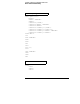
Chapter 4 Remote Interface Reference SCPI Command Summary SCPI Command Summary This section summarizes the SCPI (Standard Commands for Programmable Instruments) commands available to program the power supply over the remote interface. Refer to the later sections in this chapter for more complete details on each command. Throughout this manual, the following conventions are used for SCPI command syntax. • Square brackets ([ ]) indicate optional keywords or parameters.
Chapter 4 Remote Interface Reference SCPI Command Summary Output Setting and Operation Commands APPLy {P6V|P25V|N25V}[,{|DEF|MIN|MAX}[,{|DEF|MIN|MAX}]] APPLy? [{P6V|P25V|N25V}] INSTrument [:SELect] {P6V|P25V|N25V} [:SELect]? :NSELect {1|2|3} :NSELect? :COUPle[:TRIGger] {ALL|NONE|} :COUPle[:TRIGger]? MEASure :CURRent[:DC]? [{P6V|P25V|N25V}] [:VOLTage][:DC]? [{P6V|P25V|N25V}] OUTPut [:STATe] {OFF|ON} [:STATe]? :TRACk[:STATe] {OFF|ON} :TRACk[:STATe]? [SOURce:] CURRent[:LEVel][:IMMediat
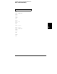
Chapter 4 Remote Interface Reference SCPI Command Summary System-Related Commands DISPlay[:WINDow] [:STATe] {OFF|ON} [:STATe]? :TEXT[:DATA] :TEXT[:DATA]? :TEXT:CLEar SYSTem :BEEPer[:IMMediate] :ERRor? :VERSion? *IDN? *RST 4 *TST? *SAV {1|2|3} *RCL {1|2|3} Calibration Commands CALibration :COUNt? :CURRent[:DATA] :CURRent:LEVel {MIN|MAX} :SECure:CODE :SECure:STATe {OFF|ON}, :SECure:STATe? :STRing :STRing? :VOLTage[:DATA] :VO
Chapter 4 Remote Interface Reference SCPI Command Summary Status Reporting Commands STATus:QUEStionable [:EVENt]? :ENABle :ENABle? :INSTrument[:EVENt]? :INSTrument:ENABle :INSTrument:ENABle? :INSTrument:ISUMmary[:EVENt]? :INSTrument:ISUMmary:CONDition? :INSTrument:ISUMmary:ENABle :INSTrument:ISUMmary:ENABle? SYSTem:ERRor? *CLS *ESE *ESE? *ESR? *OPC *OPC? *PSC {0|1} *PSC? *SRE *SRE? *STB? *WAI RS-232 Interface Commands S
Chapter 4 Remote Interface Reference SCPI Command Summary IEEE-488.
Chapter 4 Remote Interface Reference Simplified Programming Overview Simplified Programming Overview First-time SCPI users, see page 102 This section gives an overview of the basic techniques used to program the power supply over the remote interface. This section is only an overview and does not give all of the details you will need to write your own application programs. Refer to the remainder of this chapter and also chapter 6, Application Programs, for more details and examples.
Chapter 4 Remote Interface Reference Simplified Programming Overview Reading a Query Response Only the query commands (commands that end with “?”) will instruct the power supply to send a response message. Queries return either output values or internal instrument settings.
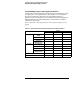
Chapter 4 Remote Interface Reference Simplified Programming Overview Programming Ranges and Output Identifiers Output setting commands require a parameter for programming ranges and an output name or an output number as the identifier of each output and most queries will return a parameter. The programming range for a parameter varies according to the selected output of the power supply. The following table lists the programming ranges, output names, and output numbers for each output.
Chapter 4 Remote Interface Reference Using the APPLy Command Using the APPLy Command The APPLy command provides the most straightforward method to program the power supply over the remote interface. You can select the specific output, output voltage, and output current all in one command. APPLy {P6V | P25V | N25V}[,{| DEF | MIN | MAX}[,{| DEF | MIN | MAX}]] This command is combination of INSTrument:SELect, [SOURce:] VOLTage, and [SOURce:]CURRent commands.
Chapter 4 Remote Interface Reference Output Setting and Operation Commands Output Setting and Operation Commands This section describes the low-level commands used to program the power supply. Although the APPLy command provides the most straightforward method to program the power supply, the low-level commands give you more flexibility to change individual parameters. See page 102 for programming ranges, output identifiers, and MIN / MAX values in the following commands.
Chapter 4 Remote Interface Reference Output Setting and Operation Commands INSTrument:COUPle[:TRIGger] {ALL | NONE |} This command defines a coupling between various logical outputs of the power supply. The couple command consists of an optional subsystem node followed by a single parameter. The only valid parameter for the optional subsystem node is TRIGger subsystem. If no node follows the couple command, TRIGger subsystem is assumed to be coupled.
Chapter 4 Remote Interface Reference Output Setting and Operation Commands INSTrument:COUPle[:TRIGger]? This query returns the currently coupled output. Returns “ALL”, “NONE”, or a list. If any output is not coupled, “NONE” is returned. If all of three outputs are coupled, “ALL” is returned. If a list of outputs is coupled, the list is returned. Measurement Commands MEASure:CURRent[:DC]? [{P6V | P25V | N25V}] This command queries the current measured at the output terminals of the power supply.
Chapter 4 Remote Interface Reference Output Setting and Operation Commands Output On/Off and Tracking Operation Commands OUTPut[:STATe] {OFF | ON} This command enables or disables all three outputs of the power supply. The state of the disabled outputs is a condition of less than 0.6 volts of opposite polarity with no load and less than 60 mA of opposite direction with a short circuit. At *RST, the output state is off. OUTPut[:STATe]? This command queries the output state of the power supply.
Chapter 4 Remote Interface Reference Output Setting and Operation Commands [SOURce:]CURRent[:LEVel]:TRIGgered[:AMPLitude] {| MINimum | MAXimum} This command programs the pending triggered current level of the power supply. The pending triggered current level is a stored value that is transferred to the output terminals when a trigger occurs. A pending triggered level is not affected by subsequent CURRent commands.
Chapter 4 Remote Interface Reference Triggering Commands Triggering Commands The power supply's triggering system allows a change in voltage and current when receiving a trigger, to select a trigger source, and to insert a trigger. Triggering the power supply is a multi-step process. • First, you must select an output with the INSTrument:SELect command and then configure the power supply for the triggered output level by using CURRent:TRIGgered and VOLTage:TRIGgered commands.
Chapter 4 Remote Interface Reference Triggering Commands • You can also trigger the power supply from the GPIB interface by sending the IEEE-488 Group Execute Trigger (GET) message. The following statement shows how to send a GET from a Agilent Technologies controller. TRIGGER 705 (group execute trigger) • To ensure synchronization when the bus source is selected, send the *WAI (wait) command.
Chapter 4 Remote Interface Reference Triggering Commands Triggering Commands INITiate[:IMMediate] This command causes the trigger system to initiate. This command completes one full trigger cycle when the trigger source is an immediate and initiates the trigger subsystem when the trigger source is bus.
Chapter 4 Remote Interface Reference System-Related Commands System-Related Commands DISPlay[:WINDow][:STATe] {OFF | ON} This command turns the front-panel display off or on. When the display is turned off, outputs are not sent to the display and all annunciators are disabled except the ERROR annunciator. The display state is automatically turned on when you return to the local mode. Press the Local key to return to the local state from the remote interface.
Chapter 4 Remote Interface Reference System-Related Commands SYSTem:ERRor? This command queries the power supply's error queue. When the front-panel ERROR annunciator turns on, one or more command syntax or hardware errors have been detected. Up to 20 errors can be stored in the error queue. See “Error Messages” in chapter 5. • Errors are retrieved in first-in-first-out (FIFO) order. The first error returned is the first error that was stored.
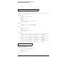
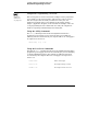
Chapter 4 Remote Interface Reference System-Related Commands *RST This command resets the power supply to its power-on state as follows: Command State CURR[:LEV][:IMM] CURR[:LEV]:TRIG DISP[:STAT] INST[:SEL] INST:COUP OUTP[:STAT] OUTP:TRAC TRIG:DEL TRIG:SOUR VOLT[:LEV][:IMM] VOLT[:LEV]:TRIG Output dependent value* Output dependent value* ON P6V NONE OFF OFF 0 BUS 0 0 *The reset operation sets the current of +6V output to 5 A and the current of +25V and -25V outputs to 1 A.