
User`s manual


Agilent E1330B Digital I/O Module Register Information 115
Appendix B
I/O This is a read/write bit. Read this bit to find the current status of the I/O line,
which is an output line to the peripheral, and the port data transceiver. If bit
6 is equal to "0", the line is FALSE and the transceiver is enabled for output.
If bit 6 is equal to "1", the line is TRUE and the transceiver is enabled for
input. This bit is equal to "1" (input) after a hardware reset. You can select
input or output by changing this bit.
Note If you are using the port handshake lines to control transfers, use the I/O
line to control the direction of data transfer to your peripheral. Make sure
that the peripheral is always enabled to send data during input transfers and
to receive data during output transfers.
CTL This is a read/write bit. Read this bit to find the current state of the CTL line.
A "1" shows the line is TRUE; a "0" shows the line is FALSE (the bit is not
normalized). When handshaking is enabled (bit 1 of the Port Transfer
Control Register is set), the CTL line is controlled by the port controller. To
prevent incorrect handshaking due to interaction with other lines, before
enabling handshaking, set the control line to FALSE.
Port Data Register The Port Data Register is a read/write register. It is used for both output and
input. Its operation depends on the state of the I/O
.
• If I/O is set for output (bit 6, Port Transfer Control Register = "0"),
data written to the Port Data Register is latched and remains until new
data is written. The current data in the Port Data Register drives the
port data bus. If you read Port Data Register, the value read is the
value last written to the register.
• If I/O is set for input (bit 6, Port Transfer Control Register ="1"), the
data read from the Port Data Register is the data transmitted by the
peripheral on the port data bus. If you write to the Port Data Register,
the data is latched for output, but the data lines are not affected until
I/O
is again set for output.
• When the Port Data Register is read, the following bits are set to "0"
on the Port Transfer Control Register: DRR (bit 0), TI (bit 5), and PI
(bit 7).
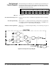
Bits 0-7 Bits 0-7 of the Port Data Register correspond to data lines D(0-7) where bit
7 is the most significant bit.
Port Address (0–3) base+14
16
, base+15
16
, base+16
16
, base+17
16
76543210
D7 D6 D5 D4 D3 D2 D1 D0