
User`s manual


Agilent E1330B Digital I/O Module Register Information 109
Appendix B
Reset and Registers
When the Digital I/O module undergoes a power on or *RST in SCPI, the
bits of the registers are put into the following states:
• The identification bytes at address 00 through 03, the Manufacturer ID
and Device ID, remain unaffected.
• The I/O bits (bit 6 of the Port Control/Status Registers (0-3)) are set to
"1", enabling all four ports for input.
• The port delay register is set to 2µs.
• The port handshake register is set to interrupt driver.
• All other bits of all registers are set to "0".
Register Definitions
You can program the Agilent E1330A/B Quad 8-bit Digital I/O module
using its hardware registers. The procedures for reading or writing to a
register depend on your operating system and programming language.
Whatever the access method, you will need to identify each register with its
address. These addresses are given in Table B-2.
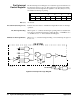
Table B-2. Register Map
Register Name Address
Manufacturer ID (MSB) 00
16
Manufacturer ID (LSB) 01
16
Device ID (MSB) 02
16
Device ID (LSB) 03
16
Card /Status/Control (MSB) 04
16
Card/Status/Control (LSB) 05
16
Address
Register Name Port 0 Port 1 Port 2 Port 3
Port Interrupt Control 08
16
09
16
0A
16
0B
16
Port Transfer Control 0C
16
0D
16
0E
16
0F
16
Port Control/Status 10
16
11
16
12
16
13
16
Port Data 14
16
15
16
16
16
17
16
Port Handshake 18
16
19
16
1A
16
1B
16
Port Delay 1C
16
1D
16
1E
16
1F
16
Port Normalization 20
16
21
16
22
16
23
16