75000 SERIES B Mainframes E1300B and E1301B User’s Manual Copyright © Agilent Technologies, Inc., 1989, 1990, 1991, 2006 Manual Part Number: E1300-90005 Microfiche Part Number: E1300-99005 Printed: February 2006 Printed in U.S.A.
Certification Agilent Technologies certifies that this product met its published specifications at the time of shipment from the factory. Agilent Technologies further certifies that its calibration measurements are traceable to the United States National Institute of Standards and Technology (formerly National Bureau of Standards), to the extent allowed by that organization’s calibration facility, and to the calibration facilities of other International Standards Organization members.
Printing History The Printing History shown below lists all Editions and Updates of this manual and the printing date(s). The first printing of the manual is Edition 1. The Edition number increments by 1 whenever the manual is revised. Updates, which are issued between Editions, contain replacement pages to correct the current Edition of the manual. Updates are numbered sequentially starting with Update 1. When a new Edition is created, it contains all the Update information for the previous Edition.
Declaration of Conformity according to ISO/IEC Guide 22 and EN 45014 Manufacturer’s Name: Agilent Technologies, Inc. Loveland Manufacturing Center Manufacturer’s Address: 815 14th Street S.W.
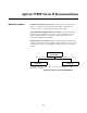
Agilent 75000 Series B Documentation Manual Descriptions Installation and Getting Started Guide. Contains step-by-step instructions for all aspects of plug-in module and mainframe installation. This guide also contains introductory programming information and examples. Agilent E1300B/E1301B Mainframe User’s Manual.
1 Related Documents Agilent Instrument BASIC User’s Handbook. Includes three books: Agilent Instrument BASIC Programming Techniques , Agilent Instrument BASIC Interfacing Techniques, and Agilent Instrument BASIC Language Reference. Using Agilent Instrument BASIC with the E1405. Contains information on the version of Agilent Instrument Basic which can be installed in ROM in your E1405B Command Module. Beginner’s Guide to SCPI.
About this Manual Manual Content Chapter 1: Getting Started Chapter 2: Using the Front Panel Chapter 3: Using the Display Terminal Interface Chapter 4: Using the Mainframe This manual shows how to use the Agilent E1300/E1301 Mainframe and how to operate and program instruments within the mainframe using SCPI (Standard Commands for Programmable Instruments) commands and IEEE 488.2 Common Commands.
Table of Contents 1. Getting Started Using This Chapter . . . . . . . . . . Mainframe Description . . . . . . . Optional Mainframe Memory . . Instrument Definition . . . . . . . . Instrument Logical Addresses . Instrument Secondary Addresses Unassigned Modules . . . . . . . Introductory Programming Examples . . . . . . . . . . . . . . . . . . . . . . . . . . . . . . . . . . . . . . . . . . . . . . . . . . . . . . . . . . . . . . . . . . . . . . . . . . . . . . . . . . . . . . . . . . . . . . . .
Using Supported Terminals . . . . . . The Supported Terminals . . . . . . Using the HP 700/22 . . . . . . . . . Using the WYSEØ WY-30œ . . . . Using Other Terminals . . . . . . . . . What “Not Supported” Means . . . Testing Terminals for Compatibility Using a Terminal Without Menus . In Case of Difficulty . . . . . . . . . . . Instrument Menus . . . . . . . . . . . . . . . . . . . . . . . . . . . . . . . . . . . . . . . . . . . . . . . . . . . . . . . . . . . . . . . . . . . . . . . . . . . . . . . .
The Service Request Bit . . . . . . . . . . . . . . . . . . . . Clearing the Service Request Enable Register . . . . . . . Standard Event Status Register . . . . . . . . . . . . . . . Unmasking Standard Event Status Bits . . . . . . . . . . . Reading the Standard Event Status Enable Register Mask Reading the Standard Event Status Register . . . . . . . . Operation Status Group . . . . . . . . . . . . . . . . . . . Reading the Condition Register . . . . . . . . . . . . . . .
*SRE < mask> . . . . . . . . . . . . . . . . . . . . . *SRE? . . . . . . . . . . . . . . . . . . . . . . . . . . . *STB? . . . . . . . . . . . . . . . . . . . . . . . . . . . *TRG . . . . . . . . . . . . . . . . . . . . . . . . . . . *TST? . . . . . . . . . . . . . . . . . . . . . . . . . . . *WAI . . . . . . . . . . . . . . . . . . . . . . . . . . . GPIB Message Reference . . . . . . . . . . . . . . . . . Go To Local (GTL) . . . . . . . . . . . . . . . . . . . Group Execute Trigger (GET) . . . . . . . . .
C. Connecting and Configuring a Display Terminal Using this Appendix . . . . . . . . . . . . . Overview . . . . . . . . . . . . . . . . . . . . Connecting a Terminal to the Mainframe . . Configuring a Terminal for the Mainframe . Starting with Default Mainframe Settings Restoring the Default Configuration . . . Configuring the Terminal . . . . . . . . . Trying it . . . . . . . . . . . . . . . . . . . Configuring the Mainframe with Menus . . . . . . . . . . . . . . . . . . . . . . . . . . . . . . . . . .
6 - Table of Contents
Chapter 1 Getting Started Using This Chapter This chapter describes the Agilent E1300B/E1301B Mainframe, defines the instrument concept, and explains how plug-in modules are designated as instruments in the mainframe. This chapter also contains introductory programming examples showing how to read and set the mainframe’s clock and calendar. This chapter contains the following sections: • Mainframe Description . . . . . . . . . . . . . . . . . . . . . . . . . . . . . . . . . 1-1 • Instrument Definition .
GPIB Trig Out: Allows an instrument to output a negative-going pulse to indicate the occurrence of some event such as closing a channel on a Switchbox Instrument. The signal levels are standard TTL (0V to 5V). This pulse can be used to synchronize external equipment to the instrument (see Chapter 5 for examples). You direct the pulse from the appropriate instrument to the Trig Out port using the OUTP:STAT ON command.
1 Instrument Definition SCPI-compatible plug-in modules installed in the mainframe are treated as independent instruments each having a unique secondary GPIB address. As shown in Figure 1-3, each instrument is assigned a dedicated error queue, input and output buffers, status registers and, if applicable, dedicated mainframe memory space for readings or data.
Instrument Logical Addresses Instruments are identified by a logical address which directly relates to its GPIB secondary address. Instruments come from the factory with a preset logical address. You can change the factory setting during installation (see the "Agilent 75000 Series B Installation and Getting Started Guide" for instructions). A single-module instrument must have its logical address set to an integer multiple of 8 (0, 8, 16, 24, ... 240).
Example: Reading the Time This program reads and prints the time from the System Instrument’s internal clock. The computer used in the example is an Agilent Series 200/300 computer with Agilent BASIC as the program language. The computer interfaces to the mainframe using the General Purpose Interface Bus (GPIB). The GPIB interface select code is 7, the GPIB primary address is 09, and the GPIB secondary address is 00 (System Instrument). Resulting in a combined address of 70900.
1-6 Getting Started
Chapter 2 Using the Front Panel Using this Chapter This chapter shows you how to use the Agilent E1301B Mainframe’s front panel keyboard and display to operate instruments in the mainframe. It contains the following sections: • • • • • • Front Panel Features . . . . . . . . . . . . . . . . . . . . . . . . . . . . . . . . . . . 2-1 Using Menus . . . . . . . . . . . . . . . . . . . . . . . . . . . . . . . . . . . . . . . . . . 2-2 Executing Commands . . . . . . . . . . . . . . . . . . . . . . . . . . . .
1 Using Menus You can access a System Instrument menu and a variety of other instrument menus (depending on installed instruments) from the front panel. These menus incorporate the most used functions but do not provide access to all of the instrument commands. If a particular function is not available from a menu, you can type the corresponding command string and execute it from the front panel. See “Executing Commands” later in this chapter for more information.
• Press Prev Menu to return to the previous menu within an instrument menu or escape from an input prompt. Press Select Instr to return to the Select an Instrument menu. Note that when you leave an instrument and return later, you return to the same menu location you were when you left. In addition, any other displayed information (instrument responses or commands being entered) will also be displayed when you return.
How to Reset the System GPIB Note: The RESET menu selection is equivalent to the DIAG:BOOT command which has the same effect as cycling power to the mainframe. Pressing Reset Instr from the System Instrument menu is equivalent to executing the *RST command which resets the System Instrument.
Using the Other Instrument Menus The instrument menus allow you to access the most-used instrument functions or to monitor an instrument (monitor mode) while it is being controlled from remote. We’ll use the Switchbox menu to show you how to use the instrument menus. Menus are available for many but not all instruments. See “Instrument Menus”, later in this chapter, for more information on a particular instrument’s menu.
How to Open/Close Channels How to Scan Channels 2-6 Using the Front Panel
How to Display Monitor Type, Description, or Reset Module How to Select Monitor Mode Using the Front Panel 2-7
Monitor Mode Monitor mode displays the status of an instrument while it is being controlled from remote. Monitor mode is useful for debugging programs. You can place an instrument in monitor mode using front panel menus, or by executing the DISP:MON:STAT ON command from the front panel or by remote. (Executing the remote DISP:MON:STAT ON command is the only way to assign the display/keyboard to an instrument from remote.
1 Executing Commands From the front panel, you can type and execute IEEE 488.2 Common Commands and SCPI Commands for the instrument presently selected by the Select an instrument menu. (However, you cannot execute a command when the display is requesting that you input information.) This is particularly useful for accessing functions not available in an instrument’s menu.
1 Key Descriptions This section explains the function of each of the front panel’s dedicated keys. If a key is not functional in a particular situation, pressing that key does nothing except to cause a beep. Users of the optional IBASIC interpreter should refer to their IBASIC manual set for additional editing functions. Menu Keys Selects the menu choice displayed directly above each key. Returns to the Select an instrument menu.
the cursor to the beginning of the line. Pressing CTRL followed by the left arrow key moves the cursor 4 character spaces to the left. Erases the character at the present cursor position (for user-entered data only). Erases the character to the left of the cursor (for user-entered data only). (Clear-to-end key.) Erases all characters from the present cursor position to the end of the input line (for user-entered data only).
1 In Case of Difficulty Problem: Problem Cause/Solution: Error -113 undefined header error occurs after entering data in response to a menu prompt. For some commands used by the menus, the data entered is appended to a command header. For example, if you enter "1" as the port number for a digital I/O module, the command used is DIG:HAND1:MODE NONE where HAND1 indicates the port number. If your entry was invalid or incorrect, error -113 occurs.
2 Instrument Menus This section contains charts showing the structure and content for all front panel instrument menus. Also shown in the charts are the SCPI or Common Commands used and descriptions of menu-controlled instrument operations. This section contains the following charts: • • • • • • • • System Instrument Menu. . . . . . . . . . . . . . . . . . . . . . . . . . . . . . . Switchbox Menu . . . . . . . . . . . . . . . . . . . . . . . . . . . . . . . . . . . . . . Scanning Voltmeter Menu . . . . .
2-14 Using the Display Terminal Interface CONFIG? SYSTEM Command(s) Used PACE BITS PARITY card number card number 9600 19200 card number card number card number XON/ OFF NONE READ card number 8 SET card number 7 card number NONE SET card number ZERO card number card number ONE READ card number card number EVEN ODD SET card number 2400 card number card number 1200 READ card number 300 SET SYST:COMM:SER[ n] :PACE NONE SYST:COMM:SER[ n] :PACE XON SYST:COMM:SER[ n] :PACE?
Using the Display Terminal Interface 2-15 Level 2 Level 3 RESET DATE TIME DEBUG card number card number card number OFF IBFULL STANDRD DIAG:BOOT SYST:DATE < date> date SET SYST:TIME < time> SYST:DATE? time SET READ SYST:TIME? VXI:WRIT < laddr> ,< reg> ,< data> VXI:READ? < laddr> ,< reg> DIAG:COMM:SER[ n] :STORE SYST:COMM:SER[ n] :CONT:RTS STAN SYST:COMM:SER[ n] :CONT:RTS IBF SYST:COMM:SER[ n] :CONT:RTS OFF SYST:COMM:SER[ n] :CONT:RTS ON SYST:COMM:SER[ n] :CONT:RTS? SYST:COMM:SER[ n
2-16 Using the Display Terminal Interface User Entry TEST card number ‡ card number ‡ card number ‡ DESCR? RESET channel list † STEP SCAN TYPE? channel list † SET_UP CLOSE CARD channel list † channel list † OPEN card number ‡ or AUTO Level 3 MONITOR Level 2 * TST? SYST:CPON < card_number> SYST:CDES? < card_number> SYST:CTYP? < card_number> TRIG TRIG:SOUR HOLD;:SCAN < channel_list> ;:INIT CLOS (@channel_list) OPEN (@channel_list) DISP:MON:CARD < card_number> ;STAT ON Command(s) Us
Notes Using the Front Panel 2-17
2-18 Using the Display Terminal Interface channel list † VDC channel list † channel list † channel list † BENDING BENPOIS POISSON channel list † POISSON FULL channel list † channel list † BENDING channel list † 392 HALF channel list † channel list † 385 MEAS:TEMP? THER,5000,< channel_list> channel list † 5K 10K MEAS:STR:FPO? < channel_list> MEAS:STR:FBP? < channel_list> , MEAS:STR:FBEN? < channel_list> MEAS:STR:HPO? < channel_list> MEAS:STR:HBEN? < channel_list> MEAS:STR:QUAR? < chann
Using the Display Terminal Interface 2-19 Level 2 Level 3 card number ‡ card number ‡ DESCR? channel list † TENSION TYPE? * TST? SYST:CDES? < card_number> SYST:CTYP? < card_number> MEAS:STR:QTEN? < channel_list> MEAS:STR:QCOM? < channel_list> MEAS:STR:UNST? < channel_list> Command(s) Used Runs self-test, displays results (+ 0= pass; any other number= fail) Displays module description Displays module ID information Tension shunt diagnostic Compression shunt diagnostic Measure bridge unstr
2-20 Using the Display Terminal Interface Measure °C of 5kΩ thermistor (4-wire measurement) MEAS:TEMP? FTH,5000 MEAS:TEMP? FTH,10000 5K 10K RTD MEAS:TEMP FRTD,92? 392 * TST? MEAS:TEMP FRTD,85? 385 Run self-test, display results (0= pass; any other number= fail) Measure °C of 100Ω RTD with alpha = 392 (4-wire measurement) Measure °C of 100Ω RTD with alpha = 385 (4-wire measurement) Measure °C of 10kΩ thermistor (4-wire measurement) Measure 4-wire ohms Measure AC volts ‡ The card number identifie
Using the Display Terminal Interface 2-21 TEST OUTPUT MONITOR Level 2 CURRENT current ‡ current ‡ current ‡ CHAN3 CHAN4 voltage † CHAN4 current ‡ voltage † CHAN3 CHAN2 voltage † CHAN1 voltage † ‡Enter current values in amps. Typical examples are: .05, + 200E-3.
2-22 Using the Display Terminal Interface DIG_I/ O Level 1 WRITE READ MONITOR Level 2 Menu Levels and Content W_BIT W_BYTE R_BIT bit (0-7), value (0,1) bit (0-7), value (0,1) bit (0-7), value (0,1) PORT1 PORT2 PORT3 data (0-255) PORT3 bit (0-7), value (0,1) data (0-255) PORT2 PORT0 data (0-255) PORT1 bit (0-7) PORT3 data (0-255) bit (0-7) PORT2 PORT0 bit (0-7) PORT1 DIG:HAND3:MODE NONE;:DIG:DATA3:BITm < value> DIG:HAND2:MODE NONE;:DIG:DATA2:BITm < value> DIG:HAND1:MODE NONE;:DIG
Notes Using the Front Panel 2-23
2-24 Using the Display Terminal Interface MONITOR COUNTER frequency ‡ TRIG:SOUR IMM;:MEAS1:PER? TRIG:SOUR IMM;:MEAS3:PER? CHAN1 CHAN3 TRIG:SOUR IMM;:MEAS3:FREQ? INP:FILT:FREQ < value> FREQ CHAN3 INP:FILT OFF TRIG:SOUR IMM;:MEAS1:FREQ? INP:FILT ON OFF INP:ISOL OFF OFF ON INP:ISOL ON SENS4:EVEN:SLOP POS SENS4:EVEN:SLOP NEG POS SENS3:EVEN:SLOP NEG NEG NEG SENS3:EVEN:SLOP POS POS SENS2:EVEN:SLOP POS SENS2:EVEN:SLOP NEG POS SENS1:EVEN:SLOP NEG NEG NEG SENS1:EVEN:SLOP POS POS SENS3
Using the Display Terminal Interface 2-25 Level 2 Level 3 CHAN4 CHAN3 CHAN2 CHAN1 CHAN3 CHAN1 FETC4? READ ‡Enter frequency value in hertz. Typical examples are: 60, 120, 1E3.
2-26 Using the Display Terminal Interface MONITOR COUNTER TRIG:SOUR IMM;:MEAS1:PER? TRIG:SOUR IMM;:MEAS2:PER? CHAN2 TRIG:SOUR IMM;:MEAS3:FREQ? CHAN3 CHAN1 TRIG:SOUR IMM;:MEAS1:FREQ? TRIG:SOUR IMM;:MEAS2:FREQ? INP:FILT OFF OFF CHAN1 INP:FILT ON ON INP:ATT 0 INP:ATT 20 0dB INP:IMP 1e6 1_MOHM 20dB INP:IMP 50 50_OHM INP:COUP AC INP:COUP DC SENS2:EVEN:SLOP NEG NEG AC SENS2:EVEN:SLOP POS POS DC CHAN2 SENS1:EVEN:SLOP POS SENS1:EVEN:SLOP NEG POS SENS2:EVEN:LEV< value> SENS1:EVEN:LEV<
Using the Display Terminal Interface 2-27 Level 2 Level 3 CHAN2 FETC2? READ * TST? TRIG:SOUR IMM;:CONF2:TOT;:INIT2 FETC1? READ START TRIG:SOUR IMM;:CONF1:TOT;:INIT1 START TRIG:SOUR IMM;:MEAS2:RAT? CHAN2 CHAN1 TRIG:SOUR IMM;:MEAS1:RAT? TRIG:SOUR IMM;:MEAS2:NWID? CHAN1 TRIG:SOUR IMM;:MEAS1:NWID? CHAN2 TRIG:SOUR IMM;:MEAS2:PWID? CHAN2 CHAN1 TRIG:SOUR IMM;:MEAS1:PWID? CHAN1 TRIG:SOUR IMM;:MEAS1:TINT? Command(s) Used TRIG:SOUR IMM;:MEAS2:TINT? User Entry CHAN2 Level 5 CHAN1 Level 4
Notes 2-28 Using the Front Panel
Chapter 3 Using the Display Terminal Interface Using this Chapter This chapter shows you how to use the Agilent E1300B and Agilent E1301B Mainframes’ Display Terminal Interface (terminal interface) to operate instruments in the mainframe. The terminal interface uses the built-in RS-232 and/or the optional Agilent E1324A Datacomm Module to provide all of the features of the Agilent E1301B’s front panel, plus comfortable keyboard position and full screen display.
1 Terminal Interface Features Figure 3-2 shows a typical terminal interface display with its function labels across the bottom of the screen. The first five function keys (f1 through f5) select instrument menu choices. Function keys f6 through f8 provide menu control and access to utility functions. The tutorials in this chapter show how to use most of the menu control and utility function keys.
1 Using Menus A System Instrument menu and a variety of other instrument menus (depending on installed instruments) are available from the terminal interface. These menus incorporate the most used functions but do not provide access to the complete functionality of an instrument. If a particular function is not available from a menu, you can type the corresponding Common Command or SCPI command string and execute it from the terminal interface.
If you make an incorrect entry in response to an input prompt, the bottom line of the Text Output Area will show an error message. When this happens, just select that menu choice again (f1 - f5 keys), re-type the correct information, and press Return. • Press PRV_MENU or ESC to return to the previous menu within an instrument menu or escape from an input prompt. Press SEL_INST to return to the Select an Instrument menu (see next item).
Using the System Instrument Menu The System Instrument menu allows you to: • • • • Set or read the system GPIB address Reset (reboot) the mainframe Display the logical addresses of installed instruments Display information about installed instruments How to Set or Read the System GPIB Address Enter new GPIB address, press Return (range= 1 through 30) SCPI command used: SYST:COMM:GPIB:ADDR < addr> Typical GPIB address SCPI command used: SYST:COMM:GPIB:ADDR? Using the Display Terminal Interface 3-5
How to Reset the System Press f1 to Reset Note: The RESET menu selection is equivalent to executing the DIAG:BOOT command which has the same effect as cycling the mainframe’s power. Pressing RST_INST from the System Instrument menu is the equivalent to sending the * RST command to the System Instrument.
How to Display Logical Addresses and Instrument Information Enter device’s logical address and press Return for individual instrument information, or just enter one space and Return, for information on all intruments. (In this case, 8 was entered) Logical address of selected device Instrument name GPIB secondary address Note: For a description of each field of the instrument information, see VXI:CONF:DLIS? in the SCPI Command Reference section.
Using the Other Instrument Menus The instrument menus allow you to access the most-used instrument functions or to monitor an instrument (monitor mode) while it is being controlled from remote. We’ll use the Switchbox menu to show you how to use the instrument menus. Menus are available for many but not all instruments. See “Instrument Menus”, later in this chapter, for more information on a particular instrument’s menu.
How to Open/Close Channels Switchbox instrument at logical address 32 (secondary address = 04) SCPI command used: OPEN < channel_list> Enter Channel List and press Return (e.g., 102 for channel 2 on card # 1) SCPI command used: CLOSE < channel_list> How to Scan Channels Press f2 to advance to the next channel in the Scan List (i.e. to trigger the instrument.) Enter Channel List and press Return (e.g.
How to Display Module Type , Description, or Reset Module Enter Card Number and press Return Enter Card Number and press Return SCPI command used: SYST:CPON < card_number> SCPI command used: SYST:CTYP? < card_number> Enter Card Number and press Return SCPI command used: SYST:CDES? < card_number> 3-10 Using the Display Terminal Interface
How to Select Monitor Mode Enter Card Number or type AUTO and press Return SCPI commands used: DISP:MON:CARD < card_number> DISP:MON:STAT ON Monitor Mode Monitor mode displays the status of an instrument while it is being controlled from remote. Monitor mode is useful for debugging programs. You can place an instrument in monitor mode using terminal interface menus, or by executing the DISP:MON:STAT ON command from the terminal interface.
Note Enabling monitor mode slows instrument operations. If the timing or speed of instrument operations is critical (such as making multimeter readings at a precise time interval), you should not use monitor mode. Table 3-1 shows the status annunciators that may appear in the bottom line of the screen in monitor mode. Some instruments also have device-specific annunciators (see the plug-in module manual for more information). Table 3-1.
1 Executing Commands From the terminal interface, you can type and execute IEEE 488.2 Common Commands and SCPI Commands for the instrument presently selected by the Select an instrument menu. (However, you cannot execute a command when the screen is requesting that you input information.) This is particularly useful for accessing functions not available in an instrument’s menu.
1 General Key Descriptions This section explains the function of each of the terminal interface’s menu, menu control, and editing keys. If a key is not functional in a particular situation, pressing that key does nothing except to cause a beep. Menu and Menu Control Keys f1 UTILS through f5 SEL_INST PRV_MENU Label menu choices for corresponding function keys. Returns to the Select an instrument menu. Returns to the previous menu level within an instrument menu or escapes from an input prompt.
Erases the character to the left of the cursor (for user-entered data only). (Clear-to-end key.) Erases all characters from the present cursor position to the end of the input line (for user-entered data only). Selects the upper-case alphabetic characters or the character shown on the top half of a key. Sets all alphabetic keys to uppercase (capitals); does not affect the other keys. To return to lowercase, press Caps Lock again.
1 Using Supported Terminals The Supported Terminals The Display Terminal Interface supports several popular terminal brands and models. This chapter will show you how to access all of the terminal interface functions described previously using your supported terminal. The following list names the supported terminals and shows where to go for more information. If your terminal isn’t named in this list, see “Using Other Terminals” in the next section. • • • • HP 700/92 . . . . . . . . . . . . . . . . . . .
Using the HP 700/22 VT100® Key Map Selecting VT100® Mode The HP 700/22 terminal emulates the DEC® VT100® or VT220® terminals. Some functions of the Display Terminal Interface have been mapped into keys with other labels. A keyboard map is provided for each of the emulation models. Use these keyboard maps to help locate the terminal interface functions. The symbols shown in the upper left corner of key each are now mapped with the function labeled in the center of each key.
VT220® Key Map Note The function keys that are normally labeled f6 through f14 are now labeled: Because the HP 700/22 keyboard has nine function keys in the center of the keyboard, f4 is mapped twice The symbols shown in the upper left corner of key each are now mapped with the function labeled in the center of each key.
Using the WYSE WY-30 With the WYSE WY-30 terminal, some functions of the Display Terminal Interface have been assigned to keys with other labels. Use this keyboard map to help locate these functions. The symbols shown in the upper left corner of key each are now mapped with the function labeled in the center of each key. Where two function key labels are shown, the one following the "/" character is accessed by pressing and holding the CTRL key while pressing the desired function key (e.g.
What “Not Supported” Means Strictly speaking, a terminal is not supported if it has not been rigorously tested with the Display Terminal Interface. There are several HP terminals which may be compatible with the terminal interface. Terminals such as the DEC® VT100® , DEC® VT220® , and WYSE ® WY-50, or emulations of these may also work properly with the terminal interface. If you have one of these terminals, try it. Here is a list of terminals you should try.
If you now see the “Select an instrument” menu labels: Go to the beginning of this chapter and try the menus. or Turn the mainframe off and then on again. Using a Terminal Without Menus You can still control instruments installed in your mainframe without using the terminal interface menus. In this case you will send Common Commands and SCPI commands to your instruments by typing them on your terminal keyboard, or through a computer interface.
To get a list of the logical addresses used in your mainframe, send the SCPI command VXI:CONF:DLAD? to the System Instrument. Then to determine what instrument is at each logical address, send the command VXI:CONF:DLIS? n for each logical address in the list (where n is a logical address). Returning to the “Select an Instrument” Prompt To return to the “Select an instrument” prompt, press and hold the CTRL key then press D.
1 In Case of Difficulty Problem: Problem Cause/Solution: Error -113 undefined header error occurs after entering data in response to a menu prompt. For some commands used by the menus, the data entered is appended to a command header. For example, if you enter "1" as the port number for a digital I/O module, the command used is DIG:HAND1:MODE NONE where HAND1 indicates the port number. If your entry was invalid or incorrect, error -113 occurs.
Notes 3-24 Using the Display Terminal Interface
2 Instrument Menus This section contains charts showing the structure and content for all terminal interface instrument menus. Also shown in the charts are the SCPI or Common Commands used and descriptions of menu-controlled instrument operations. This section contains the following charts: • • • • • • • • System Instrument Menu. . . . . . . . . . . . . . . . . . . . . . . . . . . . . . . Switchbox Menu . . . . . . . . . . . . . . . . . . . . . . . . . . . . . . . . . . . . . . Scanning Voltmeter Menu .
3-26 Using the Display Terminal Interface CONFIG? SYSTEM Command(s) Used PACE BITS PARITY card number card number 9600 19200 card number card number card number XON/ OFF NONE READ card number 8 SET card number 7 card number NONE SET card number ZERO card number card number ONE READ card number card number EVEN ODD SET card number 2400 card number card number 1200 READ card number 300 SET SYST:COMM:SER[ n] :PACE NONE SYST:COMM:SER[ n] :PACE XON SYST:COMM:SER[ n] :PACE?
Using the Display Terminal Interface 3-27 Level 2 Level 3 RESET DATE TIME DEBUG card number card number card number OFF IBFULL STANDRD DIAG:BOOT SYST:DATE < date> date SET SYST:TIME < time> SYST:DATE? time SET READ SYST:TIME? VXI:WRIT < laddr> ,< reg> ,< data> VXI:READ? < laddr> ,< reg> DIAG:COMM:SER[ n] :STORE SYST:COMM:SER[ n] :CONT:RTS STAN SYST:COMM:SER[ n] :CONT:RTS IBF SYST:COMM:SER[ n] :CONT:RTS OFF SYST:COMM:SER[ n] :CONT:RTS ON SYST:COMM:SER[ n] :CONT:RTS? SYST:COMM:SER[ n
3-28 Using the Display Terminal Interface User Entry TEST card number ‡ card number ‡ card number ‡ DESCR? RESET channel list † STEP SCAN TYPE? channel list † SET_UP CLOSE CARD channel list † channel list † OPEN card number ‡ or AUTO Level 3 MONITOR Level 2 * TST? SYST:CPON < card_number> SYST:CDES? < card_number> SYST:CTYP? < card_number> TRIG TRIG:SOUR HOLD;:SCAN < channel_list> ;:INIT CLOS (@channel_list) OPEN (@channel_list) DISP:MON:CARD < card_number> ;STAT ON Command(s) Us
Notes Using the Display Terminal Interface 3-29
3-30 Using the Display Terminal Interface channel list † VDC channel list † channel list † channel list † BENDING BENPOIS POISSON channel list † POISSON FULL channel list † channel list † BENDING channel list † 392 HALF channel list † channel list † 385 MEAS:TEMP? THER,5000,< channel_list> channel list † 5K 10K MEAS:STR:FPO? < channel_list> MEAS:STR:FBP? < channel_list> , MEAS:STR:FBEN? < channel_list> MEAS:STR:HPO? < channel_list> MEAS:STR:HBEN? < channel_list> MEAS:STR:QUAR? < chann
Using the Display Terminal Interface 3-31 Level 2 Level 3 card number ‡ card number ‡ DESCR? channel list † TENSION TYPE? * TST? SYST:CDES? < card_number> SYST:CTYP? < card_number> MEAS:STR:QTEN? < channel_list> MEAS:STR:QCOM? < channel_list> MEAS:STR:UNST? < channel_list> Command(s) Used Runs self-test, displays results (+ 0= pass; any other number= fail) Displays module description Displays module ID information Tension shunt diagnostic Compression shunt diagnostic Measure bridge unstr
3-32 Using the Display Terminal Interface Measure °C of 5kΩ thermistor (4-wire measurement) MEAS:TEMP? FTH,5000 MEAS:TEMP? FTH,10000 5K 10K RTD MEAS:TEMP FRTD,92? 392 * TST? MEAS:TEMP FRTD,85? 385 Run self-test, display results (0= pass; any other number= fail) Measure °C of 100Ω RTD with alpha = 392 (4-wire measurement) Measure °C of 100Ω RTD with alpha = 385 (4-wire measurement) Measure °C of 10kΩ thermistor (4-wire measurement) Measure 4-wire ohms Measure AC volts ‡ The card number identifie
Using the Display Terminal Interface 3-33 TEST OUTPUT MONITOR Level 2 CURRENT current ‡ current ‡ current ‡ CHAN3 CHAN4 voltage † CHAN4 current ‡ voltage † CHAN3 CHAN2 voltage † CHAN1 voltage † ‡Enter current values in amps. Typical examples are: .05, + 200E-3.
3-34 Using the Display Terminal Interface DIG_I/ O Level 1 WRITE READ MONITOR Level 2 Menu Levels and Content W_BIT W_BYTE R_BIT bit (0-7), value (0,1) bit (0-7), value (0,1) bit (0-7), value (0,1) PORT1 PORT2 PORT3 data (0-255) PORT3 bit (0-7), value (0,1) data (0-255) PORT2 PORT0 data (0-255) PORT1 bit (0-7) PORT3 data (0-255) bit (0-7) PORT2 PORT0 bit (0-7) PORT1 DIG:HAND3:MODE NONE;:DIG:DATA3:BITm < value> DIG:HAND2:MODE NONE;:DIG:DATA2:BITm < value> DIG:HAND1:MODE NONE;:DIG
Notes Using the Display Terminal Interface 3-35
3-36 Using the Display Terminal Interface MONITOR COUNTER frequency ‡ TRIG:SOUR IMM;:MEAS1:PER? TRIG:SOUR IMM;:MEAS3:PER? CHAN1 CHAN3 TRIG:SOUR IMM;:MEAS3:FREQ? INP:FILT:FREQ < value> FREQ CHAN3 INP:FILT OFF TRIG:SOUR IMM;:MEAS1:FREQ? INP:FILT ON OFF INP:ISOL OFF OFF ON INP:ISOL ON SENS4:EVEN:SLOP POS SENS4:EVEN:SLOP NEG POS SENS3:EVEN:SLOP NEG NEG NEG SENS3:EVEN:SLOP POS POS SENS2:EVEN:SLOP POS SENS2:EVEN:SLOP NEG POS SENS1:EVEN:SLOP NEG NEG NEG SENS1:EVEN:SLOP POS POS SENS3
Using the Display Terminal Interface 3-37 Level 2 Level 3 CHAN4 CHAN3 CHAN2 CHAN1 CHAN3 CHAN1 FETC4? READ ‡Enter frequency value in hertz. Typical examples are: 60, 120, 1E3.
3-38 Using the Display Terminal Interface MONITOR COUNTER TRIG:SOUR IMM;:MEAS1:PER? TRIG:SOUR IMM;:MEAS2:PER? CHAN2 TRIG:SOUR IMM;:MEAS3:FREQ? CHAN3 CHAN1 TRIG:SOUR IMM;:MEAS1:FREQ? TRIG:SOUR IMM;:MEAS2:FREQ? INP:FILT OFF OFF CHAN1 INP:FILT ON ON INP:ATT 0 INP:ATT 20 0dB INP:IMP 1e6 1_MOHM 20dB INP:IMP 50 50_OHM INP:COUP AC INP:COUP DC SENS2:EVEN:SLOP NEG NEG AC SENS2:EVEN:SLOP POS POS DC CHAN2 SENS1:EVEN:SLOP POS SENS1:EVEN:SLOP NEG POS SENS2:EVEN:LEV< value> SENS1:EVEN:LEV<
Using the Display Terminal Interface 3-39 Level 2 Level 3 CHAN2 FETC2? READ * TST? TRIG:SOUR IMM;:CONF2:TOT;:INIT2 FETC1? READ START TRIG:SOUR IMM;:CONF1:TOT;:INIT1 START TRIG:SOUR IMM;:MEAS2:RAT? CHAN2 CHAN1 TRIG:SOUR IMM;:MEAS1:RAT? TRIG:SOUR IMM;:MEAS2:NWID? CHAN1 TRIG:SOUR IMM;:MEAS1:NWID? CHAN2 TRIG:SOUR IMM;:MEAS2:PWID? CHAN2 CHAN1 TRIG:SOUR IMM;:MEAS1:PWID? CHAN1 TRIG:SOUR IMM;:MEAS1:TINT? Command(s) Used TRIG:SOUR IMM;:MEAS2:TINT? User Entry CHAN2 Level 5 CHAN1 Level 4
Notes 3-40 Using the Display Terminal Interface
Chapter 4 Using the Mainframe Using this Chapter This chapter shows how to use the mainframe’s Pacer function, how to change the primary GPIB address, and how to synchronize internal and external instruments using the mainframe’s Event In and Trigger Out ports. This chapter also discusses how mainframe memory is used by installed instruments. Where possible, examples show only the command string sent to the instrument (no information about a computer language or interface is shown).
• SOUR:PULS:COUN sets the number of Pacer cycles. Specify from 1 to 8388607 cycles or specify INF for a continuous output. • SOUR:PULS:PER sets the period of each Pacer cycle. You can specify periods from 500ns to 8.3 seconds. • TRIG:SOUR sets the trigger source. The Pacer signal is output whenever the trigger event occurs (specified by the TRIG:SOUR command) and the INIT:IMM command has been executed.
Figure 4-2. Pacer Trigger States 1 Changing the Primary GPIB Address You can set the mainframe’s primary GPIB address to any integer value between 0 and 30. The address is set to 9 at the factory. (See Chapter 2 for instructions on setting/reading the GPIB address from the front panel.) The following command sets the mainframe’s primary GPIB address to 12.
Example: Synchronizing an Internal Instrument to an External Instrument This example uses the mainframe’s Trig Out and Event In ports to synchronize an external multimeter to a multiplexer installed in the mainframe. Connections are shown in Figure 4-3. The multimeter’s Voltmeter Complete port outputs a pulse whenever the multimeter has finished a reading. The multimeter’s External Trigger port allows the multimeter to be triggered by a negative going TTL pulse.
multimeter to an internal multiplexer. Connections are shown in Figure 4-4. This method synchronizes the computer to the instruments and relies on the computer to enter each reading and advance to the next channel in the scan list. The sequence of operation is: 1. INIT (line 50) closes channel number 100. 2. The channel closure causes a pulse on Trig Out which triggers the multimeter to take a reading. 3. When the reading is complete it is sent to the computer (lines 60 to 80). 4.
Figure 4-4. Synchronizing Internal/External Instruments and Computer 1 Mainframe Data Memory When power is applied or the system rebooted (DIAG:BOOT command), mainframe memory is automatically configured to provide a predefined amount of memory for any installed instruments that require memory space. For example, each multimeter instrument within the mainframe is allocated enough memory to store 100 readings. Mainframe memory is also automatically re-allocated upon demand while programming.
Example: Storing and Retrieving Data From Mainframe Memory. This example shows how to use mainframe memory to store 15 readings made using an Agilent E1326A Multimeter. After the readings are stored, they are retrieved by the computer and displayed.
address. You will then know the starting address , and (from the …NRAM:CRE < size> command) the length of the NRAM segment. Example: Allocating an NRAM segment and locating it. This example shows how to allocate a small 128 byte NRAM segment. In addition, it shows how to determine the starting address of that segment.
Using :DOWNload and :UPload? to Access Data Caution Data Formats for :DOWNload The command DIAG:DOWNload < address> ,< data_block> is used to store data into the NRAM segment. The command DIAG:UPLoad? < address> ,< byte_count> is used to retrieve data from the NRAM segment. The address parameter in …DOWNload and …UPLoad? can specify any address within the capability of the System Instrument’s control processor.
Example: Storing and Retrieving data using DOWNload and UPLoad.
Chapter 5 Downloading Device Drivers About this Chapter This chapter describes the procedure for using downloadable device drivers with the Agilent E1405 Command Module. This functionality was added so that SCPI capability for new register based devices could be added to the Command Module without having to update an internal set of ROMs. This chapter contains the following sections: • • • • • • • • • • About this Chapter. . . . . . . . . . . . . . . . . . . . . . . . . . . . . . . . . . . . .
GPIB bus GPIB bus GPIB bus GPIB Figure 5-1.
1 Memory Configuration Before attempting to download any device drivers you should understand how memory is affected when you specify a size for one or more types of RAM. There are three types of RAM that you can allocate in the mainframe: • RAM disk (RDISK) • Non-volatile RAM (NRAM) • Driver RAM (DRAM) Figure 5-2 shows the positioning of these areas in memory. User Non-volatile RAM and RAM Disk both occupy higher memory addresses than the Driver RAM.
1 Download Program Configuration If you will not be using the default configurations for downloading, you will need to edit the configuration file to match your system configuration. If the default values shown below are correct for your setup, you can proceed to the appropriate downloading instructions. The configuration defaults for MS-DOS systems are: • • • • • • • • Download program searches for drivers in current directory. Execution Log is OFF (log to screen only).
specify a file name here, the driver downloader will log to the screen and to the specified file. DRIVER FILE = specifies the driver file or files to download. The default is to download all device driver files found in the directory specified by DIRECTORY = . If the driver downloader finds one line in this format, it will assume that you are specifying entries and will only download the listed entries. This configuration item can have multiple lines.
1 Downloading Drivers in MS-DOS Systems The device driver download program VXIDLD.EXE provided on the disk with the driver files for use with an RS-232 interface must be run from MS-DOS. It will set up the the required device driver memory and any other memory partitions defined in the configuration file, reboot the system, and download the device driver.
1 Downloading Drivers in GPIB Systems with IBASIC NOTE The device driver download program AUTOST provided on the disk with the driver files for use with GPIB must be run from IBASIC (Instrument Basic). It will set up the the required device driver memory and any other memory partitions defined in the configuration file, reboot the system, and download the device driver. This program will issue a warning and abort if any errors are encountered.
1 Downloading Drivers in GPIB Systems with BASIC The device driver download program VXIDLD_GET provided on the disk with the driver files for use with GPIB must be run from an BASIC other than IBASIC. It will set up the the required device driver memory and any other memory partitions defined in the configuration file, reboot the system, and download the device driver.
1 Downloading Multiple Drivers The driver downloader software automatically checks for the existence of other drivers when it is run. If there are device drivers present, it will abort the process and inform you that you must first clear the other device drivers out of the mainframe and then download all of the required drivers at once.
1 Manually Downloading a Driverdown manual Preparing Memory for Manual Downloading Download programs are supplied for use with the system setups described earlier in this chapter. If you have a system setup that does not allow the use of one of the supplied download programs (for instance, if you are using a Macintosh® computer), you will need to manually download the driver. The details of this process will be different for different system setups, but the basic procedures are outlined below.
Manually Downloading Over GPIB Manually downloading a driver over GPIB is fairly straightforward. This discussion assumes that the downloadable device driver has been supplied by Agilent. Drivers supplied by Agilent are formatted so that you just need to transfer the driver to command module memory. You must also have the driver on media that is accessible to the host computer that will be controlling the download.
If you are going to use any other setting, you must set up the appropriate settings in the System Instrument using the following commands COMM:SER[n]:REC:BAUD < rate> COMM:SER[n]:REC:SBITS < bits> DIAG:COMM STOR NOTE Pacing the Data sets BAUD rate sets number of stop bits saves settings so they will be kept through a reboot.
handshake mode is enabled, the System Instrument will not transmit characters when either the CTS (Clear to Send) or the DSR (Data Set Ready) lines are not asserted. This acts to pace the System Instrument output. NOTE The E1405 Command Module RS-232 interface is implemented as a DTE (Data Terminating Equipment). Since most computer RS-232 interfaces are also implemented as DTEs, a cable that does line swapping (null modem cable) is usually used to connect the computer to the instrument.
Transmitting Using a CAT Command On HP-UX systems you can use the cat command to transfer the device driver. The appropriate device file must exist. All shell commands are assumed to be executed from either the /bin/sh or /bin/ksh shell. 1. Start a process that opens the device file to be used. This process should keep the device file open long enough for the transfer to begin. This step is done so that the following command to set the device file configurations will remain in effect for the transfer.
Figure 5-3.
5-16 Downloading Device Drivers
Chapter 6 Controlling Instruments Using GPIB About this Chapter This chapter shows how to control instruments in the mainframe from an external computer using IEEE 488.2 Common Commands and the GPIB interface. This includes how to monitor instrument status, interrupt the computer, and synchronize one or more instruments to an external computer. Command references for the supported IEEE 488.2 Common Commands and IEEE 488.2 GPIB Messages are located near the end of this chapter.
2 Status System Structure The instrument status structure monitors important events for an instrument such as when an error occurs or when a reading is available.
The Status Byte Register As shown in Figure 4-1, the Status Byte register is the highest-level register in the status structure. This register contains bits which summarize information from the other status groups. NOTE The bits in the other status group registers must be specifically enabled to be reported in the Status Byte register. Refer to "Unmasking Standard Event Status Bits" (later in this chapter) for more information.
Table 4-1 shows each of the Status Byte register bits and describes the event that will set each bit. Table 4-1. Status Byte Register Reading the Status Byte Register Bit Number Decimal Weight 0 1 Instrument Specific (not used by most instruments) 1 2 Instrument Specific (not used by most instruments) 2 4 Instrument Specific (not used by most instruments) 3 8 Questionable Data Status Group Summary Bit.
The following program reads the system instrument’s Status Byte register using the GPIB Serial Poll command. 10 P= SPOLL(70900) 20 PRINT P 30 END Service Request Enable Register Read Status Byte Register using Serial Poll, place weighted sum in P Print weighted sum The Service Request Enable register is used to "unmask" bits in the Status Byte register. When an unmasked Status Byte register bit is set to ’1’, a service request is sent to the computer over GPIB.
Standard Event Status Register NOTE The Standard Event Status Register in the Standard Event status group monitors the instrument status events shown in Table 4-2. When one of these events occurs, it sets a corresponding bit in the Standard Event Status Register. The Standard Event Status Register bits are not reported in the Status Byte Register unless unmasked by the Standard Event Status Enable Register. Refer to the section "Unmasking Standard Event Status Bits" for more information. Table 4-2.
unmasked, an GPIB service request (SRQ) will be generated. ("Interrupting the External Computer", later in this chapter contains an example program which demonstrates this sequence). Note that the Standard Event Status Register bits that are not unmasked still respond to their corresponding conditions. They do not, however, set bit 5 in the Status Byte Register.
Table 4-3. Operation Status Group - Condition Register Bit Number Decimal Weight 0 1 Calibrating 1 2 Settling 2 4 Ranging 3 8 Sweeping 4 16 Measuring 5 32 Waiting for TRG 6 64 Waiting for ARM 7 128 Correcting 8 256 9-12 13-14 15 Reading the Condition Register Description Interrupt acknowledged (System Instrument) Instrument Dependent Reserved Always zero When an event monitored by the Condition register has occurred or is occurring, a corresponding bit in the register is set.
Bits in the Operation Status Group Event register which are set can be determined with the command: STATus:OPERation:EVENt? This command returns the decimal weighted sum of the set bit(s).
SUB Intr_resp B= SPOLL(70900) OUTPUT 70900; "STAT:OPER:EVEN?" ENTER 70900; E OUTPUT 70900; "DIAG:INTR:RESP?" ENTER 70900; R . . . SUBEND 1 Clearing Status The *CLS command clears all status registers (Standard Event Status Register, Standard Operation Status Event Register, Questionable Data Status Event Register) and the error queue for an instrument. This clears the corresponding summary bits (bits 3, 5, & 7) and the instrument-specific bits (bits 0, 1, & 2) in the Status Byte Register.
Example: Interrupting when an Error Occurs This program shows how to interrupt an external computer whenever an error occurs for the instrument being programmed which, in this example, is a multimeter at secondary address 03.
1 Synchronizing an External Computer and Instruments The *OPC? and *OPC commands (operation complete commands) allow you to maintain synchronization between an external computer and an instrument. The *OPC? query places an ASCII character 1 into the instrument’s output queue when all pending instrument operations are finished. By requiring the computer to read this response before continuing program execution, you can ensure synchronization between one or more instruments and an external computer.
Example: Synchronizing an External Computer and Two Instruments using the * OPC command. This example uses the *OPC command and serial poll to synchronize an external computer and two instruments (DAC at secondary address 09; Scanning Voltmeter at secondary address 03). The advantage to using this method over *OPC? query method is that the computer can do other operations while it is waiting for the instrument(s) to complete operations.
6-14 Controlling Instruments Using GPIB
Chapter 7 System Instrument Command Reference About This Chapter This chapter describes the Standard Commands for Programmable Instruments (SCPI) command set and the IEEE 488.2 Common Commands for the System Instrument. The System Instrument is part of the Agilent E1300/E1301 Mainframe’s internal control processor and is therefore always present in a Mainframe. This chapter contains the following sections: • • • • • Command Types. . . . . . . . . . . . . . . . . . . . . . . . . . . . . . . . . . . . . .
Command Separator A colon (:) always separates one command from the next lower level command as shown below: ROUTe:SCAN:MODE? Colons separate the root command from the second level command (ROUTe:SCAN) and the second level from the third level (SCAN:MODE?). Abbreviated Commands The command syntax shows most commands as a mixture of upper and lower case letters. The upper case letters indicate the abbreviated spelling for the command. For shorter program lines, send the abbreviated form.
(e.g., 123, 123E2, -123, -1.23E2, .123, 1.23E-2, 1.23000E- 01). Special cases include MIN, MAX, and INFinity. The Comments section within the Command Reference will state whether a numeric parameter can also be specified in hex, octal, and/or binary. # H7B, # Q173, # B1111011 • Boolean parameters represent a single binary condition that is either true or false (e.g., ON, OFF, 1, 0). Any non-zero value is considered true. Discreet parameters select from a finite number of values.
ABORt 1 SCPI Command Reference This section describes the SCPI commands for the System Instrument. Commands are listed alphabetically by subsystem and also within each subsystem. A command guide is printed in the top margin of each page. The guide indicates the first command listed on that page. ABORt The ABORT subsystem is a part of the System Instrument’s trigger system. ABORT resets the trigger system from its Wait For Trigger state to its Idle state and aborts any pacer pulse train in progress.
DIAGnostic DIAGnostic Subsystem Syntax The DIAGnostic subsystem allows control over the System Instrument’s internal processor system (:BOOT, and :INTerrupt), the allocation and contents of User RAM, and, disc volume RAM (:NRAM, and :RDISk), and allocation of the built-in serial interface (:COMM:SER:OWNer).
DIAGnostic:BOOT:COLD :BOOT:COLD DIAGnostic:BOOT:COLD causes the System Instrument to restart (re-boot). Configurations stored in non-volatile memory and RS-232 configurations are reset to their default states: • DRAM, NRAM, and RDISk memory segments are cleared • Serial Interface parameters set to: – – – – – – – BAUD 9600 BITS 8 PARity NONE SBITs 1 DTR ON RTS ON PACE XON • Serial 0 Owner = system NOTE Resetting the serial interface parameters takes about 0.
DIAGnostic :BOOT[:WARM] :BOOT[:WARM] Comments DIAGnostic:BOOT[:WARM] causes the System Instrument to restart (re-boot) using the current configuration stored in non-volatile memory. The effect is the same as cycling power. • The System Instrument goes through its power-up self tests. • The non-volatile system state is used for configuration wherever applicable.
DIAGnostic:COMMunicate :SERial[0][:OWNer]? :COMMunicate :SERial[0][:OWNer]? Comments Example DIAGnostic:COMMunicate:SERial[0][:OWNer]? Returns the current "owner" of the built-in serial interface. The values returned will be; "SYST", "IBAS", or "NONE". • Related Commands: DIAGnostic:SERial[:OWNer] Determine which instrument has the serial interface.
DIAGnostic :DOWNload:CHECked [:MADDress] :DOWNload:CHECked [:MADDress] Parameters Comments DIAGnostic:CHECked:DOWNload[:MADDress] < address> ,< data> writes data into a non-volatile User RAM segment starting at address using error correction. The User RAM segment is allocated by the DIAG:NRAM:CREate or DIAG:DRAM:CREate command.
DIAGnostic:DOWNload:CHECked [:MADDress] Byte Format Each byte sent with this command is expected to be in the following format: Bit # 7 6 Control Bit 5 4 Check Bits 3 2 1 0 Data Bits • Control Bit is used to indicate the serial driver information such as clear, reset, or end of transmission. This bit is ignored by the regular 488.2 driver . The control bit should be one for regular data. • Check Bits are used to detect and correct a single bit error.
DIAGnostic :DOWNload:CHECked :SADDress :DOWNload:CHECked :SADDress Parameters Comments DIAGnostic:CHECked:DOWNload:SADDress < address> ,< data> writes data to non-volatile User RAM at a single address specified by address using error correction. It can also write to devices with registers in the A16 address space.
DIAGnostic:DOWNload:CHECked :SADDress Byte Format Each byte sent with this command is expected to be in the following format: Bit # 7 6 Control Bit 5 4 Check Bits 3 2 1 0 Data Bits • Control Bit is used to indicate the serial driver information such as clear, reset, or end of transmission. This bit is ignored by the regular 488.2 driver. The control bit should be one for regular data. • Check Bits are used to detect and correct a single bit error. The control bit is not included in the check.
DIAGnostic :DOWNload [:MADDress] :DOWNload [:MADDress] Parameters Comments DIAGnostic:DOWNload[:MADDress] < address> ,< data> writes data into a non-volatile User RAM segment starting at address. The User RAM segment is allocated by the DIAG:NRAM:CREate command.
DIAGnostic:DOWNload:SADDress Example Loading Dynamic Configuration information into an allocated RAM segment.
DIAGnostic :DRAM:AVAilable? Example Downloading Data to a Single Address Location This program downloads an array with the data 1, 2, 3, 4, 5 to register 32 on a device with logical address 40 in VXIbus A16 address space. DIM Dnld_data(1:5) Dimension controller array DATA 1,2,3,4,5 READ Dnld_data(* ) Load data into controller array "DIAG:DOWN:SADD # H1FCA20,# 210"; This line is sent without termination.
DIAGnostic:DRAM:CREate :DRAM:CREate Parameters Comments DIAGnostic:DRAM:CREate < size> < num_drivers> creates a non-volatile RAM area for loading instrument drivers. DIAGnostic:DRAM:CREate 0 removes the RAM segment when the system is re-booted. Parameter Name Parameter Type Range of Values Default Units size numeric 0 to available RAM or MIN| MAX none num_drivers numeric 0 to available RAM or MIN| MAX| DEF 8 • size is the number of bytes to be allocated to DRAM use.
DIAGnostic :DRIVer:LOAD < driver_block> :DRIVer:LOAD < driver_block> Parameters Comments DIAGnostic:DRIVer:LOAD < driver_block> loads the instrument driver contained in the driver_block into a previously created DRAM segment. Parameter Name Parameter Type Range of Values Default Units driver_block arbitrary block program data See "Parameter Types" at the beginning of this chapter. none • driver_block is the actual binary driver data to be transferred.
DIAGnostic:DRIVer :LIST[:type]? :DRIVer :LIST[:type]? Parameters DIAGnostic:DRIVer:LIST[:type]? lists all drivers from the specified table found on the system. If no parameter is specified, all driver tables are searched and the data from each driver table is separated from the others by a semicolon.
DIAGnostic :INTerrupt:ACTivate :INTerrupt:ACTivate Parameters Comments DIAGnostic:INTerrupt:ACTivate < mode> enables an interrupt on the VXI backplane interrupt line specified by DIAG:INT:SET[n] to be acknowledged. Parameter Name Parameter Type Range of Values Default Units mode boolean 0| 1| OFF| ON none • When an interrupt occurs and has been acknowledged, the response is read with the DIAGnostic:INTerrupt:RESPonse? command.
DIAGnostic:INTerrupt:SETup[n]? • ON or 1 specify that interrupt handling is to be set up for the specified interrupt line. OFF or 0 indicate that interrupt handling of the specified line is to be done by the operating system. • Related Commands: DIAG:INT:ACT, DIAG:INT:PRIority[n], DIAG:INT:RESP? • *RST Condition: DIAG:INT:SETup[n] OFF (for all lines) Example Setup and wait for VXI interrupt response on line 2. DIAG:INT:PRI2 5 DIAG:INT:SETUP2 ON . . .
DIAGnostic :INTerrupt:PRIority[n] :INTerrupt:PRIority[n] Parameters Comments DIAGnostic:INTerrupt:PRIority[n] [< level> ] gives a priority level to the VXI interrupt line specified by [n] in …PRIority[n]. Parameter Name Parameter Type Range of Values Default Units level numeric 1 through 7| MIN| MAX| DEF none • The priority of an interrupt line determines which line will be acknowledged first in the event that more than one line is interrupting.
DIAGnostic:INTerrupt:RESPonse? :INTerrupt:RESPonse? Comments DIAGnostic:INTerrupt:RESPonse? Returns the interrupt acknowledge response (STATUS/ID word) from the highest priority VXI interrupt line. • The value returned is the response from the interrupt acknowledge cycle (STATUS/ID word) of a device interrupting on one of the interrupt lines set up with the DIAG:INT:SET[n] command. • Bits 0 through 7 of the STATUS/ID word are the interrupting device’s logical address.
DIAGnostic :NRAM:ADDRess? :NRAM:ADDRess? Comments DIAGnostic:NRAM:ADDRess? Returns the starting address of the non-volatile User RAM segment allocated using DIAG:NRAM:CREate. • DIAG:NRAM:CREAte does not allocate the RAM segment until after a subsequent re-boot. To get accurate results, execute DIAG:NRAM:ADDRess? after the re-boot.
DIAGnostic:NRAM:CREate? :NRAM:CREate? DIAGnostic:NRAM:CREate? [MIN | MAX] Returns the current or allowable (MIN | MAX) size of the User non-volatile RAM segment. Comments • DIAG:NRAM:CRE does not allocate driver RAM until a subsequent re-boot. To get accurate results, execute DIAG:NRAM:CRE? after the re-boot. • Related Commands: DIAG:NRAM:ADDRess?, DIAG:NRAM:CREate Example Check the size of the User RAM segment.
DIAGnostic :POKE :POKE Parameters Comments DIAGnostic:POKE < address> ,< width> ,< data> writes data (number of bits given by width) starting at address. Parameter Name Parameter Type Range of Values Default Units address numeric 0 to 16,777,215 (# HFFFFFF) none width numeric 8| 16| 32 none data numeric 8 to 32 bit integer none • Address specifies a location within the range of the control processor’s addressing capability.
DIAGnostic:RDISk:CREate :RDISk:CREate Parameters Comments DIAGnostic:RDISk:CREate < size> Allocates memory for a RAM disc volume. The RAM disc volume is defined for use only by the IBASIC option. Parameter Name Parameter Type Range of Values Default Units size numeric 0 to available RAM or MIN| MAX none • The RAM disc segment will only be created after the System Instrument has been re-booted (cycle power or execute DIAG:BOOT).
DIAGnostic :UPLoad[:MADDress]? :UPLoad[:MADDress]? Parameters Comments DIAGnostic:UPLoad[:MADDress]? < address> ,< byte_count> Returns the number of bytes specified by byte_count, starting at address. Parameter Name Parameter Type Range of Values Default Units address numeric 0 to 16,777,215 (# HFFFFFE) none byte_count numeric 0 to (999,999,998) none • Address may be specified in decimal, hex (# H), octal (# Q), or binary (# B) formats.
DIAGnostic:UPload:SADDress? :UPload:SADDress? Parameters Comments DIAGnostic:UPLoad:SADDress? < address> ,< byte_count> Returns the number of bytes specified by byte_count, at address. Parameter Name Parameter Type Range of Values Default Units address numeric 0 to 16,777,215 (# HFFFFFE) none byte_count numeric 0 to (999,999,998) none • Address may be specified in decimal, hex (# H), octal (# Q), or binary (# B) formats.
INITiate [:IMMediate] INITiate The INITiate command subsystem controls the initiation of the trigger system for one or more trigger cycles. INITiate enables while ABORt disables the trigger system. The TRIGger command subsystem controls the behavior of the trigger system while it is enabled. Subsystem Syntax [:IMMediate] Comments INITiate [:IMMediate] INITiate:IMMediate changes the trigger system from the Idle state to the Wait For Trigger state. • If TRIGger:SOURce is IMMediate, the Pacer starts.
[SOURce]:PULSe:COUNt [SOURce] The System Instrument contains a Pacer which produces TTL level pulses. The SOURCE command subsystem controls the number and period of these pulses. The output of the Pacer is available at the rear-panel BNC connector labeled “Pacer Out”.
[SOURce] :PULSe:PERiod :PULSe:PERiod Parameters Comments SOURce:PULSe:PERiod < period> sets the period of the pulse(s) to be generated by the Pacer. Parameter Name Parameter Type Range of Values Default Units pweiod numeric 500E-9 to 8.388607 or MIN| MAX second • The resolution of period is 500E-9 seconds. • The Pacer waveform is a square wave with the output high for the first half of the period, and low for the final half.
STATus :OPERation :CONDition? STATus The STATus subsystem commands access the condition, event, and enable registers in the Operation Status group and the Questionable Data group. Subsystem Syntax STATus :OPERation :CONDition? :ENABle < event> :ENABle? [:EVENt]? :PRESet :QUEStionable :CONDition? :ENABle < event> :ENABle? [:EVENt]? :OPERation :CONDition? STATus:OPER:COND? returns the state of the condition register in the Operation Status group.
STATus :OPERation:ENABle? • Bit 8 is the only bit used in the condition register (by the System Instrument), therefore, it is the only bit which needs to be unmasked in the event register. Specifying the "bit weight" for the event unmasks the bit. The bit weight is 256 and can be specified in decimal, hexadecimal (# H), Octal (# Q) or binary (# B). • When the summary bit is sent, it sets bit 7 in the Status Byte register.
STATus :PRESet Example Reading the Event Register STAT:OPER:EVEN? enter statement :PRESet Example STATus:PRESet sets each bit in the enable register (standard operation status group) to ’0’. Presetting the Enable Register STAT:PRES :QUESTionable query if bit(s) is set preset enable register The STATus:QUEStionable commands are supported by the system instrument, however, they are not used by the System Instrument. Queries of the Questionable Data condition and event registers will always return + 0.
SYSTem :BEEPer[:IMMediate] SYSTem The SYSTEM command subsystem for the System Instrument provides for: • Configuration of the RS-232 interface • Control and access of the System Instrument’s real time clock/calendar (SYST:TIME, SYST:TIME?, SYST:DATE, SYST:DATE?). • Access to the System Instrument’s error queue (SYST:ERR?). • Configuring the communication ports (GPIB and serial).
SYSTem:COMMunicate :GPIB:ADDRess :COMMunicate :GPIB:ADDRess Parameters Comments SYSTem:COMMunicate:GPIB:ADDRess < address> sets the primary address of the Instrument’s GPIB port. Parameter Name Parameter Type Range of Values Default Units address numeric must round to 0 to 30 none • The value of < address> is effective after the System Instrument has received a < new line> following the SYST:COMM:GPIB:ADDR command. < new line> can be a line-feed or END (EOI signal).
SYSTem :COMMunicate :SERial[n] :CONTrol :DTR • Serial communication settings for the Agilent E1324A Datacomm interface can be stored in its on-board non-volatile EEROM only after the DIAG:COMM:SER[n]:STORe command is executed. These settings are used at power-up and DIAG:BOOT[:WARM]. • DIAG:BOOT:COLD will set the serial communication parameters to the following defaults: – – – – – – – Example BAUD 9600 BITS 8 PARity NONE SBITs 1 DTR ON RTS ON PACE XON Setting baud rate for plug-in card 2.
SYSTem:COMMunicate :SERial[n] :CONTrol :DTR? :COMMunicate :SERial[n] :CONTrol :DTR? Example SYSTem:COMMunicate:SERial[n]:CONTrol:DTR? returns the current setting for DTR line control. Checking the setting of DTR control. SYST:COMM:SER0:CONT:DTR? enter statement :COMMunicate :SERial[n] :CONTrol :RTS Parameters Comments statement enters the string "ON", "OFF", "STAN", or "IBF" SYSTem:COMMunicate:SERial[n]:CONTrol:RTS < Rts_cntrl> controls the behavior of the Request To Send output line.
SYSTem :COMMunicate :SERial[n] :CONTrol :RTS? :COMMunicate :SERial[n] :CONTrol :RTS? Example SYSTem:COMMunicate:SERial[n]:CONTrol:RTS? returns the current setting for RTS line control. Checking the setting of RTS control. SYST:COMM:SER0:CONT:RTS? enter statement :COMMunicate :SERial[n] [:RECeive] :BAUD Parameters Comments statement enters the string "ON", "OFF", "STAN", or "IBF" SYSTem:COMMunicate:SERial[n][:RECeive]:BAUD < baud_rate> Sets the baud rate for the serial port.
SYSTem:COMMunicate :SERial[n] [:RECeive] :BITS :COMMunicate :SERial[n] [:RECeive] :BITS Parameters Comments SYSTem:COMMunicate:SERial[n][:RECeive]:BITS < bits> Sets the number of bits to be used to transmit and receive data. Parameter Name Parameter Type Range of Values Default Units bits numeric 7| 8| MIN| MAX none • Attempting to set bits to other than those values shown will result in an error -222.
SYSTem :COMMunicate :SERial[n] [:RECeive] :PACE [:PROTocol] :COMMunicate :SERial[n] [:RECeive] :PACE [:PROTocol] Parameters Comments SYSTem:COMMunicate:SERial[n][:RECeive]:PACE[:PROTocol] < protocol> enables or disables receive pacing (XON/XOFF) protocol.
SYSTem:COMMunicate :SERial[n] [:RECeive] :PACE :THReshold :STARt :COMMunicate :SERial[n] [:RECeive] :PACE :THReshold :STARt Parameters Comments SYSTem:COMMunicate:SERial[n][:RECeive]:PACE:THReshold:STARt < char_count> configures the input buffer level at which the specified interface may send the XON character (ASCII 1116), assert the DTR line, and/or assert the RTS line.
SYSTem :COMMunicate :SERial[n] [:RECeive] :PACE :THReshold :STOP :COMMunicate :SERial[n] [:RECeive] :PACE :THReshold :STOP Parameters Comments SYSTem:COMMunicate:SERial[n][:RECeive]:PACE:THReshold:STOP < char_count> configures the input buffer level at which the specified interface may send the XOFF character (ASCII 1316), de-assert the DTR line, and/or de-assert the RTS line.
SYSTem:COMMunicate :SERial[n] [:RECeive] :PARity :CHECk :COMMunicate :SERial[n] [:RECeive] :PARity :CHECk Parameters Comments SYSTem:COMMunicate:SERial[n][:RECeive]:PARity:CHECk < check_cntrl> controls whether or not the parity bit in received serial data frames will be considered significant. Parameter Name Parameter Type Range of Values Default Units check_cntrl boolean 0| 1| OFF| ON none • When check_cntrl is set to 0 or OFF, received data is not checked for correct parity.
SYSTem :COMMunicate: SERial[n] [:RECeive] :PARity [:TYPE] • The following table defines each value of type: Value Definition EVEN If …PARity:CHECK is ON, the received parity bit must maintain even parity. The transmitted parity bit will maintain even parity. ODD If …PARity:CHECK is ON, the received parity bit must maintain odd parity. The transmitted parity bit will maintain odd parity. ZERO If …PARity:CHECK is ON, the received parity bit must be a zero. The transmitted parity bit will be a zero.
SYSTem:COMMunicate :SERial[n] [:RECeive] :PARity [:TYPE]? :COMMunicate :SERial[n] [:RECeive] :PARity [:TYPE]? Example SYSTem:COMMunicate:SERial[n][:RECeive]:PARity[:TYPE]? returns the type of parity checked and generated.
SYSTem :COMMunicate :SERial[n] [:RECeive] :SBITs? :COMMunicate :SERial[n] [:RECeive] :SBITs? Example SYSTem:COMMunicate:SERial[n][:RECeive]:SBITs? [MIN | MAX] returns: • The current stop bit setting if no parameter is sent. • The maximum allowable setting if MAX is sent. • The minimum allowable setting if MIN is sent. Querying the current stop bit configuration.
SYSTem:COMMunicate :SERial[n]:TRANsmit :PACE [:PROTocol] :COMMunicate :SERial[n]:TRANsmit :PACE [:PROTocol] Parameters Comments SYSTem:COMMunicate:SERial[n]:TRANsmit:PACE[:PROTocol] < protocol> enables or disables the transmit pacing (XON/XOFF) protocol. Parameter Name Parameter Type Range of Values Default Units protocol discrete XON| NONE none • For an Agilent E1324A, AUTO is always ON.
SYSTem :DATE? • Related Commands: SYST:TIME, SYST:TIME?, SYST:DATE? • *RST Condition: *RST does not change the setting of the calendar. Example Setting the system Date SYST:DATE 1991,09,08 :DATE? set SEP 8, 1991 SYSTem:DATE? [MIN| MAX,MIN| MAX,MIN| MAX] returns: • When no parameter is sent: the current system date in the form + YYYY,+ MM,+ DD, where YYYY can be the year 1980 through 2079, MM can be the month 1 through 12, and DD can be the day 1 through 31.
SYSTem:TIME :TIME Parameters Comments SYSTem:TIME < hour> ,< minute> ,< second> sets the E1300/E1301 mainframe’s internal clock. Parameter Name Parameter Type Range of Values Default Units hour numeric must round to 0 to 23 none minute numeric must round to 0 to 59 none second numeric must round to 0 to 60 none • Related Commands: SYST:DATE, SYST:DATE?, SYST:TIME? • *RST Condition: *RST does not change the Command Module’s real time clock.
TRIGger :DELay TRIGger The TRIGger command subsystem controls the behavior of the trigger system once it is initiated (see INITiate command subsystem).
TRIGger[:IMMediate] [:IMMediate] Comments TRIGger:IMMediate will cause a trigger cycle to occur immediately, provided that the trigger system has been initiated (INITiate). • Related Commands: ABORt, INITiate • *RST Condition: This command is an event and has no *RST condition. Example Triggering the Pacer. TRIG:SOUR HOLD trigger source is TRIG command output 1000 Pacer pulses pulse period set to .1 second start Pacer .75 sec after trigger go to Wait For Trigger state trigger Pacer to output pulses.
TRIGger :SOURce? Comments • The following table explains the possible choices. Parameter Value Source of Trigger BUS Group Execute Trigger (GET) bus command, *TRG common command, or TRIGger command. EXTernal “Event In” signal at rear panel BNC connector, or TRIGger command. HOLD Only the TRIGger command will cause trigger. IMMediate The trigger signal is always true (continuous triggering).
VXI:CONFigure :DLADdress? VXI The VXI command subsystem provides for: • Determining the number, type, and logical address of the devices (instruments) installed in the E1300/E1301 mainframe. • Direct access to VXIbus A16 registers within devices installed in the Mainframe.
VXI :CONFigure:DLISt? :CONFigure:DLISt? VXI:CONF:DLIS? [< logical_addr> ] returns information about the device specified by logical_addr. Response data is in the form: n1, n2, n3, n4, n5, n6, c1, c2, c3, c4, c5, s1, s2, s3, s4 Where the fields above are defined as: n fields Indicate numeric data response fields. c fields Indicate character data response fields. s fields Indicate string data response fields. n1 Device’s Logical Address. A number from 0 to 255. n2 Commander’s Logical Address.
VXI:CONFigure :DNUMber? Parameters Comments Parameter Name Parameter Type Range of Values Default Units logical_addr numeric 0-255 (or nothing) none • When logical_addr is not specified, VXI:CONF:DLIS? returns information for each of the devices installed, separated by semicolons. If the Command Module is not the resource manager, it returns information on only the devices in its servant area.
VXI :CONFigure :HIERarchy? :CONFigure :HIERarchy? NOTE VXI:CONF:HIER? Returns current hierarchy configuration information about the selected logical address. The individual fields of the response are comma separated. If the information about the selected logical address is not available from the destination device (i.e., the requested device is not in the mainframe) then Error -224 ("parameter error") will be set and no response data will be sent.
VXI:CONFigure :HIERarchy:ALL? • Cards which are part of a combined instrument such as a switchbox or scanning voltmeter always return the same manufacturer’s comments as the first card in the instrument. Information in the other fields correspond to the card for which the Logical Address was specified.
VXI :CONFigure :INFormation? registers) which are present on the device. -1 indicates that the device has no A16 memory. • A24 memory offset: an integer between -1 and 16777215 inclusive. Indicates the base address for any A24 registers which are present on the device. -1 indicates that the device has no A24 memory. • A32 memory offset: an integer between -1 and 4294967295 inclusive. Indicates the base address for any A32 registers which are present on the device.
VXI:CONFigure :INFormation:ALL? :CONFigure :INFormation:ALL? Comments :CONFigure :LADDress? Comments :CONFigure :NUMBer? Comments :READ? Parameters Comments VXI:CONF:INF:ALL? Returns the static information about all logical addresses. The information is returned in the order specified in the response to VXI:CONF:LADD?. The information about multiple logical adddresses will be semicolon separated and follow the IEEE 488.2 response message format. Individual fields of the output are comma separated.
VXI :REGister:READ? • Related Commands: VXI:WRITE, VXI:REG:READ? Example Read from one of a device’s configuration registers VXI:READ? 8,0 read ID register on device at Logical Address 8 enter value from device register enter statement :REGister:READ? Parameters Comments VXI:REG:READ? < register> returns the contents of the specified 16 bit register at the selected logical address as an integer (see VXI:SELect).
VXI:REGister:WRITe :REGister:WRITe Parameters Comments VXI:REG:WRITe? < register> ,< data> writes to the specified 16 bit register at the selected logical address (see VXI:SELect). The data is a 16 bit value specified as a numeric value in the range of -32768 to 32767 or 0 to 65535. The register is specified as the byte address of the desired register or optionally as the register name.
VXI :SELect :SELect Parameters Comments VXI:SELect < logical_addr> specifies the logical address which is to be used by many subsequent commands in the VXI subsystem. Parameter Name Parameter Type Range of Values Default Units logical_addr numeric 0 through 255 none • The *RST default value for logical_addr is that no logical address is selected (i.e., -1).
VXI:WRITe :WRITe Parameters Comments VXI:WRITe < logical_addr> ,< register_addr> ,< data> allows access to the entire 64 byte A16 register address space for the device specified by logical_addr. Since the VXIbus system is byte-addressed, while the registers are 16 bits wide, registers are specified by even addresses only. This method of identifying registers follows the VXIbus standard format.
1 Common Command Reference This section describes the IEEE-488.2 Common Commands that can be used to program instruments in the mainframe. Commands are listed by command groups in the summary table below, and alphabetically in the rest of this section. Examples are shown when the command has parameters or returns a response; otherwise the command string is as shown in the headings in this section. For additional information on any Common Commands, refer to the IEEE Standard 488.
* CLS * DMC < name_string> , < command_block> Clear Status Command. The *CLS command clears all status registers (Standard Event Status Register, Standard Operation Event Status Register, Questionable Data Event Register) and the error queue for an instrument. This clears the corresponding summary bits (bits 3, 5, & 7) and the instrument-specific bits (bits 0, 1, & 2) in the Status Byte Register.
* ESE? Example * ESR? Example Standard Event Status Enable Query. Returns the weighted sum of all enabled (unmasked) bits in the Standard Event Status Register. 10 OUTPUT 70900;"* ESE?" 20 ENTER 70900;A 30 PRINT A 40 END Standard Event Status Register Query. Returns the weighted sum of all set bits in the Standard Event Status Register. After reading the register, *ESR? clears the register.
* IDN? Identity. Returns the device identity. The response consists of the following four fields (fields are separated by commas): • • • • Manufacturer Model Number Serial Number (returns 0 if not available) Firmware Revision (returns 0 if not available) The *IDN? command returns the following command string for the E1301B: AGILENT,E1301B,0,A,07.00 This command will return the following string for the E1300B: AGILENT,E1300B,0,A,07.
NOTE The System Instrument no longer implements the *LRN? command. Attempting to have the System Instrument execute this command will generate an error -113 “Undefined header”. * OPC Operation Complete. Causes an instrument to set bit 0 (Operation Complete Message) in the Standard Event Status Register when all pending operations have been completed.
* RCL < state number> Recall stored state. Recalls a stored state from memory and configures the instrument to that state. States are stored using the *SAV command. Example * RMC < name_string> OUTPUT 70900;"* RCL 4" Recalls instrument state number 4 Remove Individual Macro Command. Purges an individual macro identified by the name_string parameter.
* SRE? Example Status Register Enable Query. Returns the weighted sum of all enabled (unmasked) events (those enabled to assert SRQ) in the Status Byte Register. 10 OUTPUT 70900;"* SRE?" 20 ENTER 70900;A 30 PRINT A 40 END * STB? Comments Example Sends Status Register Enable query Places response in variable Prints response Status Byte Register Query. Returns the weighted sum of all set bits in the Status Byte Register.
1 GPIB Message Reference Go To Local (GTL) Comments Examples This section describes IEEE-488.1 defined messages and their affect on instruments installed in the mainframe. The examples shown are specifically for HP 9000 Series 200/300 computers using BASIC language. Any IEEE-488 controller can send these messages; however, the syntax may be different from that shown here. Places an instrument in local state.
Device Clear (DCL) or Selected Device Clear (SDC) DCL clears all instruments in the mainframe. SDC clears a specific instrument. The purpose of DCL or SDC is to prepare one or more instruments to receive and execute commands (usually *RST). DCL or SDC do the following to each instrument: • Clear the input buffer and output queue. • Reset the command parser. • Disable any operation that would prevent *RST from being executed. • Disable the Operation Complete and Operation Complete Query modes.
Remote Sets the GPIB remote enable line (REN) true which places an instrument in the remote state. Comments • The REMOTE 709ss (ss = secondary address) command places the instrument in the remote state. The REMOTE 7 command, does not, by itself, place the instrument in the remote state. After sending the REMOTE 7 command, the instrument will only go into the remote state when it receives its listen address. • In most cases, you will only need the REMOTE command after using the LOCAL command.
System Instrument 1 Command Quick Reference The following tables summarize SCPI and IEEE 488.2 Common (*) commands for the Agilent E1300/E1031 Mainframe System Instrument. SCPI Commands Quick Reference Command Description ABORt [IMMediate] Abort Pacer output. DIAGnostic :BOOT :COLD Restarts System processor, clears stored configurations. [:WARM] Same as cycling power. :COMMunicate :SERial[0] [:OWNer] [SYSTem| IBASic| NONE] Allocates the built-in serial interface.
System Instrument SCPI Commands Quick Reference Command Description :NRAM :ADDRess? Returns starting address of the User non-volatile RAM. :CREate < Creates a User non-volatile RAM segment. size> | MIN| MAX :CREate? [MIN| MAX] :PEEK? < :POKE < address> | MIN| MAX,< width> address> | MIN| MAX,< width> ,< data> Returns the current or allowable size of User NVRAM. Returns an 8, 16, or 32 bit value from memory. Stores an 8, 16, or 32 bit value to RAM.
System Instrument SCPI Commands Quick Reference Command Description SYSTem :BEEPer [:IMMediate] Sound beeper (fixed duration and tone). :COMMunicate :GPIB :ADDRess Sets the primary address of the communications port. :ADDRess? Returns GPIB address or min| max allowed value. :SERial[n] :CONTrol :DTR ON| OFF| STANdard| IBFull Sets mode for modem control line DTR. :DTR? Returns current mode of DTR line. :RTS ON| OFF| STANdard| IBFull Sets mode for modem control line RTS.
System Instrument SCPI Commands Quick Reference Command Description TRIGger :DELay < numeric value> Sets delay between trigger and first Pacer pulse. :DELAy? [MIN| MAX] Returns current trigger delay or MIN| MAX allowable value. [:IMMediate] Sets trigger source for timer/pacer. :SLOPe [NEGATIVE] For compatibility only. Accepts only NEGATIVE. :SLOPe? Returns the string NEG. :SOURce EXTernal| IMMediate| BUS| HOLD Trigger source is GET or *TRIG. :SOURce? Returns current trigger source.
System Instrument IEEE 488.
7–80 Command Quick Reference
Appendix A Specifications Mainframe Specifications Pacer (50% duty cycle): Real-time Clock: Trigger Input: Non-volatile added memory storage lifetime: Slots: EMC, RFI, Safety: Programmable intervals: 500 nsec to 8.389 sec with 500 nsec resolution. Accuracy: First pulse after trigger: 0.01% of programmed time + 600 to 850 nsec. Additional pulses: 0.01% of programmed time ± 50 nsec. Number of pulses: 1 through 8388607 or continous. Drive capability: VLO ≤ 0.75 V @ 4 mA VHI ≥ 3.
Size: inches 6.97 7.44 16.75 20.1 22.38 Height without feet Height with feet Width Depth Depth with terminal blocks mm 177 189 426 510 569 Weight: Net Max per modules Power: Line voltage: Fused at: Consumption: E1300B 7.4 kg 1.3 kg E1301B 7.8 kg 1.3 kg 115 or 230 Vac @ 50 to 400 Hz 3 A @ 115 Vac 1.5 A @ 230 Vac E1300B (empty) 27 W, 52 VA E1301B (empty) 31 W, 57 VA Any combination of Agilent Series B modules can be powered and cooled by the Agilent 75000 Series B mainframe.
SCPI Conformance Information The Agilent E1300/1301B conforms to SCPI-1990.0 In documentation produced prior to June 1990, these SCPI commands are labeled as TMSL commands. The following tables list all the SCPI conforming, approved, and non-SCPI commands that the E1300/1301B can execute. Individual commands may not execute without having the proper plug-in module installed in the E1300/ 13301B. Each plug-in module manual describes the commands that apply to that module.
Multimeter Commands The following tables apply to the Agilent E1326A and E1326B. Table A-3. Multimeter SCPI-1990.
Table A-5.
Counter Commands The following tables apply to the Agilent E1332A 4 Chanel Counter/Totalizer and the Agilent E1333A 3 Channel Universal Counter. Table A-6. Agilent E1332A SCPI-1990.
Table A-8. Agilent E1333A SCPI-1990.
D/A Converter Commands The following tables apply to the Agilent E1328A 4 Channel D/A Converter. Table A-10. Agilent E1328A SCPI-1990.0 Confirmed Commands CALibration :STATe :STATe? SYSTem :ERRor? :VERSion? STATus :QUEStionable :CONDition? [:EVENt]? :ENABle :ENABle? :OPERation :CONDition? [:EVENt]? :ENABle :ENABle? Table A-11.
Digital I/O Commands The following tables apply to the Agilent E1330A Quad 8-bit Digital I/O Module. Table A-12. Agilent E1330A SCPI-1990.0 Confirmed Commands STATus :QUEStionable :CONDition? [:EVENt]? :ENABle :ENABle? :OPERation :CONDition? [:EVENt]? :ENABle :ENABle? :PREset SYSTem :ERRor? :VERSion? Table A-13.
System Instrument Commands Table A-14. System Instrument SCPI-1990.
Table A-17.
A-12 Specifications
Appendix B Error Messages Using This Appendix This appendix shows how to read an instrument’s error queue, discusses the types of command language-related error messages, and provides a table of all of the System Instrument’s error messages and their probable causes. • Reading an Instrument’s Error Queue . . . . . . . . . . . . . . . . . . . . B-1 • Error Types . . . . . . . . . . . . . . . . . . . . . . . . . . . . . . . . . . . . . . . . . . . B-2 • Start-up Error Messages . . . . . . . . . . . . . . .
1 Error Types Negative error numbers are language-related and categorized as shown below. Positive error numbers are instrument specific and for the System Instrument are summarized in Table B-2. For other instruments, refer to their own user’s manual for a description of error messages. Table B-1.
Table B-2.
Code 2110 Config error 10, Insufficient system memory 2111 Config error 11, Invalid instrument address 2113 Config error 13, Logical address or IACK switch set wrong Config warning, Sysfail detected Config error 30, Pseudo instrument logical address unavailable Config error 32, File system start up failed Config warning, Non-volatile RAM contents lost Config warning, Driver RAM contents lost Unexpected interrupt from non-message based card Interrupt line has not been set up 2129 2130 2131 2145 2148 22
1 Start-up Error Messages Start-up errors are most often generated just after the mainframe is powered-up or re-booted (DIAG:BOOT command). If you have an Agilent E1301B, or an Agilent E1300B with a terminal connected to the Display Terminal Interface (built-in RS-232 only), you can read these errors on the front panel or terminal. If you have an Agilent E1300B and no terminal, then you must access this error information by sending the VXI:CONF:DLIS? command over GPIB.
B-6 Error Messages
Appendix C Connecting and Configuring a Display Terminal Using this Appendix This appendix shows you how to configure the mainframe and a supported terminal to operate with the Display Terminal Interface. Using the Display Terminal Interface is discussed in Chapter 3. • • • • Overview . . . . . . . . . . . . . . . . . . . . . . . . . . . . . . . . . . . . . . . . . . . . . C-1 Connecting a Terminal to the Mainframe . . . . . . . . . . . . . . . . . . C-1 Configuring a Terminal for the Mainframe. . . . .
Agilent Agilent E1300B/E1301B Mainframe Agilent 10833A, B or C to Connect to GPIB Agilent Agilent E1300B/E1301B Mainframe Agilent Agilent Agilent E1300B/E1301B Mainframe Agilent 24542H Agilent 24542H Figure C–1 Connecting a Terminal to the Mainframe C-2 Connecting and Configuring a Display Terminal
1 Configuring a Terminal for the Mainframe Starting with Default Mainframe Settings We’ll first set the terminal’s serial communication parameters to match the mainframe’s default settings. If the mainframe is new and its factory default values are still set, the terminal will be ready to use. If the settings have been changed and you don’t know what they are (Agilent E1300 with no front panel), you will restore them to their default values.
Trying it Turn on the mainframe while watching the terminal’s display. After the mainframe finishes its self-test, the terminal should display "Select an instrument". If not, the mainframe’s communication parameters are not set to the default values. Go back to “Restoring the Default Configuration”. 1 Configuring the Mainframe with Menus After you have your terminal communicating with your mainframe at the default settings you may want to change to settings which are better for your installation.
How to Use the Serial Interface Menus Press READ to find out the current setting Press SET to change the current setting Each SET Menu will have two or more choices Enter Card Number press Return (0 for built-in, 1-7 for a plug-in) Read the BAUD rate Enter Card Number press Return (0 for built-in, 1-7 for a plug-in) The setting is now in volatile RAM storeage. See the “How to Store Interface Settings” Menu Chart for non-volatile storage which maintains settings through power cycles.
How to Store the Serial Interface Configuration Enter Card Number press Return. Card Number 0 for built-in stores settings into non_volatile RAM.
D Appendix Sending Binary Data Over RS-232 About this Appendix This appendix describes the procedure for sending pure binary data over an RS-232 interface. The formatting described is used in the DIAG:DOWN:CHEC:MADD, DIAG:DOWN:CHEC:SADD, and DIAG:DRIV:LOAD:CHEC commands. this appendix contains the following main sections. • About this Appendix . . . . . . . . . . . . . . . . . . . . . . . . . . . . . . . . . . D-1 • Formatting Binary Data for RS-232 Transmission. . . . . . . . . .
Table D-1.
3. Send "SI SYSTEM" and a carriage return to get the attention of the System Instrument. 4. Send < CTRL-C> to clear the system. 5. Send "*RST" and a carriage return to put the System Instrument in a known state. The program must then send the binary data. This block of data should include the command "DIAG:DOWN:CHEC" followed by the address to download to and an IEEE 488.2 arbitrary block header. This block header can be either definite or indefinite.
D-4 Sending Binary Data Over RS-232
Index ! 3-Channel Universal Counter Menu (front panel), 2-26 - 2-27 Menu (terminal interface), 3-38 - 3-39 4-Channel Counter/Totalizer Menu (front panel), 2-24 - 2-25 Menu (terminal interface), 3-36 - 3-37 4-Channel D/A Converter Menu (front panel), 2-21 Menu (terminal interface), 3-33 5 1/2 Digit Multimeter Menu (front panel), 2-20 Menu (terminal interface), 3-32 60-second menu tutorial front panel, 2-2 terminal interface, 3-3 :DRIVer:LOAD, 7-17 :DRIVer:LOAD:CHECked, 7-17 A Abbreviated Commands, 7-2 ABORt
*SAV, 7-70 *SRE, 7-70 *SRE?, 7-71 *STB?, 7-71 *TRG, 7-71 *TST?, 7-71 *WAI, 7-71 Common Commands functional groupings, 7-65 COMMunicate:GPIB :ADDRess, 7-36 :ADDRess?, 7-36 COMMunicate:SERial[0] :OWNer, 7-7 :OWNer?, 7-8 COMMunicate:SERial[n] :CONTrol:DTR, 7-37 :CONTrol:DTR?, 7-38 :CONTrol:RTS, 7-38 :CONTrol:RTS?, 7-39 :RECeive:BAUD, 7-39 :RECeive:BAUD?, 7-39 :RECeive:BITS, 7-40 :RECeive:BITS?, 7-40 :RECeive:PACE:PROTocol, 7-41 :RECeive:PACE:PROTocol?, 7-41 :RECeive:PACE:THReshold:STARt, 7-42 :RECeive:PACE:THR
DIAG:PEEK?, 7-24 DIAG:POKE, 7-25 DIAG:RDIS:ADD?, 7-25 DIAG:RDIS:CRE, 7-26 DIAG:RDIS:CRE?, 7-26 DIAG:UPL:SADD?, 7-28 DIAG:UPL[:MADD]?, 7-27 DRIV:LIST:ROM?, 7-18 DRIV:LIST?, 7-18 DIAGnostic:DRIVer:LIST:RAM?, 7-18 DIAGnostic:DRIVer:LIST:ROM?, 7-18 DIAGnostic:DRIVer:LIST?, 7-18 Display instrument information (terminal interface), 3-5 control/editing keys (front panel), 2-10 instrument information (front panel), 2-3 instrument logical addresses (front panel), 2-3 instrument logical addresses (terminal interface)
F Files:VXIDLD.
tutorial, 2-2 Menu (terminal interface) 3-Channel Universal Counter, 3-38 - 3-39 4-Channel Counter/Totalizer, 3-36 - 3-37 Quad 8-Bit Digital Input/Output, 3-34 4-Channel D/A Converter, 3-33 5 1/2 Digit Multimeter, 3-32 control keys, 3-14 instrument, 3-25 keys, 3-14 Scanning Voltmeter, 3-30 - 3-31 Switchbox, 3-28 System Instrument, 3-26 - 3-27 tutorial, 3-3 Mode, monitor, 3-11 Mode, monitor (front panel), 2-8 Modules, unassigned, 1-4 Monitor a Switchbox (front panel), 2-5 a Switchbox (terminal interface), 3-
S SA, terminal interface command, 3-21 Scan channels (front panel), 2-5 Switchbox, terminal interface, 3-8 Scanning Voltmeter Menu (front panel), 2-18 - 2-19 Voltmeter Menu (terminal interface), 3-30 - 3-31 SCPI Commands, 7-1 Format, 7-1 Reference, 7-4 SDC (selected device clear), 7-73 Secondary addresses, instrument, 1-4 SELect, 7-63 Select Address command (terminal interface), 3-21 Select Instrument command (terminal interface), 3-21 SELect?, 7-63 Selected device clear (SDC), 7-73 Selecting instruments, w
SYST:COMM:SER[n]:REC:PACE:THR:STOP, 7-43 SYST:COMM:SER[n]:REC:PACE:THR:STOP?, 7-43 SYST:COMM:SER[n]:REC:PAR:CHEC, 7-44 SYST:COMM:SER[n]:REC:PAR:CHEC?, 7-44 SYST:COMM:SER[n]:REC:PAR[:TYPE?], 7-46 SYST:COMM:SER[n]:REC:SBIT, 7-46 SYST:COMM:SER[n]:REC:SBIT?, 7-47 SYST:COMM:SER[n]:TRAN:AUTO, 7-47 SYST:COMM:SER[n]:TRAN:AUTO?, 7-47 SYST:COMM:SER[n]:TRAN:PACE:PROT, 7-48 SYST:COMM:SER[n]:TRAN:PACE:PROT?, 7-48 SYST:COMM:SERial[n]:CONT:RTS, 7-38 SYST:DATE, 7-48 SYST:DATE?, 7-49 SYST:ERRor?, 7-49 SYST:TIME, 7-50 SYST:T
Index-8