
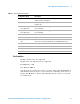
Technical data

56 Agilent U7232A DisplayPort Electrical Performance Compliance Test Application
6 Source Transition Time Differential Tests (Informative)
Source Transition Time Differential Tests
Transition time testing measures the rise time and fall time across the
outputs of a differential data lane. The transition is defined as the time
interval between the normalized 20% and 80% amplitude levels.
The transition time test should be performed at all bit rates supported
without pre- Emphasis for 400 mV differential voltage swing. The source
pattern should be a PRBS 7 waveform. This applies to one, two, and four
lane operation with all functional lanes being tested. (Reference: Table 3.10
VESA DisplayPort Standard).
Test P ro ce du re
1 Start the automated testing application as described in “Starting the
DisplayPort Electrical Performance Compliance Test Application" on
page 22.
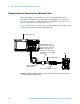
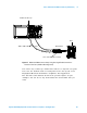
2 Connect the W2641A test fixture or other appropriate fixture to the
device under test (DUT).
3 If you are using one connection, connect the probe to one channel. If
you are using two connections, connect the two probes to two channels
of the oscilloscope. If you are using four connections, connect the four
probes to four channels of the oscilloscope.
4 Connect the SMA to SMP cable to the SMA probe head of one of the
probes and to the data lane connector on the W2641A fixture that you
want to test.
5 Connect the other SMA to SMP cable to the other SMA probe head and
to the data lane on the W2641A test fixture that you want to test.
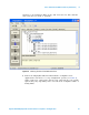
6 In the DisplayPort Compliance Test Application, click the Set Up tab.
7 Set the Test Mode, Test Type, DUT Definition Settings, Fixture Type,
Connection Type and Number of Channels according to the type of
testing being done. Source tests are available in all the 3 test modes -
Compliance Conditions Only, User Defined Conditions and Targeted
Characterization Testing.
8 This is an Informative test, therefore, the Hide Informative Tests
checkbox must be un- checked.