
Technical data

DC Power Supply Operation 3
Protection Functions
U3606A User’s and Service Guide 79
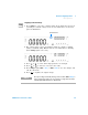
4 Press Shift > Save or Voltage (Protect) to save the changes. “donE” will be
briefly displayed in the upper secondary display. The display will then
return to normal.
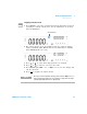
5 Alternatively, press Shift > Exit or Shift > Protect to exit the edit mode
without saving.
Checking the OVP operation
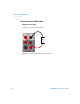
To check OVP operation, raise the regulated output current slowly. Watch
the voltage drawn by the load as it reaches near the trip point. Then very
gradually increase the output current using the directional keys until the
OVP circuit trips. This will disable the U3606A output, cause the CC
annunciator to flash, and the OV and Error annunciator to illuminate.
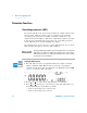
The “triP” message appears on the display after a few seconds of
inactivity.
NOTE
• The OVP feature is always enabled by default whenever you select
constant current mode. You can disable the OVP feature by disabling
the output protection state from the utility menu. See Chapter 4,
“Setting the output protection state,” starting on page 122 for more
information.
• If the OVP value is set to a lesser value than the OV value, the OV value
will be adjusted to equal the OVP value.
• The OVP value is not applicable for square-wave output.
• The OVP value is limited by the range selected. Press Shift > Range to
select an appropriate range. You can only select a range when the
output is disabled (the SBY annunciator is illuminated).