
Technical data

6 Calibration Procedures
Adjustments procedures
212 U3606A User’s and Service Guide
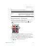
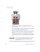
6 Press to start the adjustment. The display “CALib” in the lower
secondary display starts flashing to indicate that the calibration is in
progress.
• Successful completion of the adjustment is indicated by a short beep
and the primary display briefly showing “PASS”.
• An adjustment failure is indicated by a long beep, the primary
display showing “FAiL” and a calibration error number appearing in
the upper secondary display. Correct the problem and repeat this
procedure.
7 Repeat step 3 through step 6 for each output adjustment item shown in
Table 6- 12.
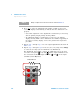
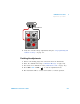
8 Repeat step 3 through step 7 for the S1 (30 V/1 A) range. Press Voltage
to select the S1 range (the S1 annunciator is illuminated).
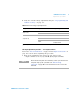
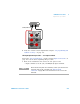
For adjustment item “LOAd”, connect an additional 30 Ω, 50 W load
across the front panel (red) and (black) output terminals. Leave
the connections from the output terminals ( and ) to the input
terminals (V and LO) intact.
NOTE
Always complete tests in the same order as shown in Table 6-12.
OUT
SBY
30 Ω, 50 W load