
Technical data

4 System Related Operation
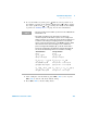
Utility Menu Summary
124 U3606A User’s and Service Guide
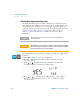
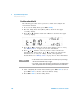
4 Press Voltage or Current if you wish to configure the ramp signal
parameters for CV or CC output. (The CV or CC annunciator
illuminates respectively when selected.)
5 Select an appropriate output range by pressing Shift > Range. The ramp
signal amplitude end position is limited by the range selected. (The S1
or S2 annunciator illuminates respectively when selected.)
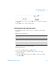
6 Press or to change the ramp signal amplitude end position. See
“Editing values” on page 110 for more information.
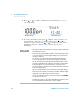
7 Press or until the cursor is position on the ramp signal number
of steps. Press or to change the number of steps for the ramp
signal to increment from zero to the amplitude end position. See
“Editing values” on page 110 for more information.
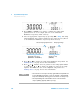
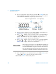
Amplitude end position
(NN.NNN V or N.NNNN A)
Number of steps
(NNNNN)
Ramp signal rangeCV/CC ramp signal parameters
NOTE
• The increment of each step in the ramp signal will be the amplitude end
position divided by the number of steps. For example, a 15 V amplitude
end position divided by 100 steps gives an increment of 0.15 V per step.
• The ramp dwelling time selected will be fastest of the instrument
output capability. (Typically ~300 ms per step.)