
Technical data

3 DC Power Supply Operation
Remote Sensing
104 U3606A User’s and Service Guide
Enable remote sensing
To configure the U3606A for remote sensing:
1 Turn off the U3606A.
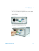
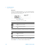
2 Remove the connections between the U3606A sensing (S+ and S–) and
output (+ and –) terminals. Using a shielded two- wire cable, connect
the U3606A sensing terminals to the load as shown in Figure 3- 3.
Observe the polarity when connecting the sensing leads to the load.
3 Turn on the U3606A.
4 Press Voltage to select the constant voltage mode. Use the directional
keys to select the appropriate constant voltage value. See “Constant
voltage (CV) mode” on page 74 for more information.
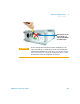
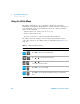
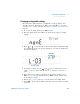
5 Press Shift > EXT to enable remote sensing. When the U3606A is
operating in remote sensing mode, the EXT annunciator on the front
panel is illuminated.
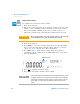
6 Press to regulate the output voltage.
7 Press Shift > EXT again to disable remote sensing.
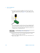
CAUTION
Do not use the shield as one of the sensing conductors. The other end
of the shielded two-wire cable should be left unconnected.
EXT annunciator
OUT
SBY
NOTE
If the power supply is operated with remote sensing and either the positive
or negative load wire is not connected, an internal protection circuit will
activate and shut down the power supply. To resume operation, turn the
power supply off, connect the open load wire, and turn on the power
supply.