
Technical data

3 DC Power Supply Operation
Remote Sensing
102 U3606A User’s and Service Guide
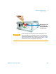
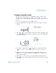
4 Loosen the top screws with a Phillips screw driver and connect the
rear output terminal block sensing (S+ and S–) and output (+ and –)
terminals to the load as shown in Figure 3- 3 using a shielded two- wire
cable.
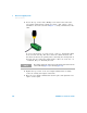
Do not use the shield as one of the sensing conductors. Ground the shield
at the U3606A end only. The other end of the shield should be left
unconnected. Observe the polarity when connecting the sensing leads to
the load. You can connect the output leads to either one of the two + or
– terminals. They are internally shorted.
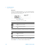
5 Tighten the top screws of the rear output terminal block to firmly
secure the sensing and output connections.
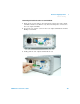
6 Place the rear output terminal block back in place and tighten the two
captive screws again.
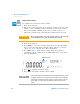
NOTE
The sensing outputs (S+ and S–) must not be left unconnected. It must be
connected locally (Figure 3-4) or remotely (Figure 3-3).