
User manual


2.3.39 AcqrsD1_configFCounter
Purpose
Configures a frequency counter measurement
Parameters
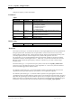
Input
Name Type Description
instrumentID ViSession Instrument identifier
signalChannel ViInt32 Signal input channel
type ViInt32 Type of measurement
= 0 Frequency (default)
= 1 Period (1/frequency)
= 2 Totalize by Time
= 3 Totalize by Gate
targetValue ViReal64 User-supplied estimate of the expected value, may be
0.0 if no estimate is available.
apertureTime ViReal64 Time in sec, during which the measurement is
executed, see discussion below.
reserved ViReal64 Currently ignored
flags ViInt32 Currently ignored
Return Value
Name Type Description
status ViStatus Refer to Table 2-1 for error codes.
Discussion
The Frequency mode (type = 0) measures the frequency of the signal applied to the selected ‘signalChannel’
during the aperture time. The default value of ‘apertureTime’ is 0.001 sec and can be set to any value
between 0.001 and 1000.0 seconds. A longer aperture time may improve the measurement accuracy, if the
(externally applied) reference clock has a high accuracy and/or if the signal slew rate is low.
The ‘targetValue’ is a user-supplied estimated of the expected result, and helps in choosing the optimal
measurement conditions. If the supplied value is < 1000.0, and > 0.0, then the instrument will not use the
HF trigger mode to divide the input frequency. Otherwise, it divides it by 4 in order to obtain a larger
frequency range.
The Period mode (type = 1) is equal to the frequency mode, but the function AcqrsD1_readFCounter
returns the inverse of the measured frequency. If the ‘targetValue’ is < 0.001 (1 ms), then the instrument
will not use the HF trigger mode, otherwise it does.
The Totalize by Time mode (type = 2) counts the number of pulses in the signal applied to the selected
‘signalChannel’ during the time defined by ‘apertureTime’. The ‘targetValue’ is ignored.
The Totalize by Gate mode (type = 3) counts the number of pulses in the signal applied to the selected
‘signalChannel’ during the time defined by signal at the I/O A or I/O B inputs on the front panel. The gate is
open while the signal is high, and closed while the signal is low (if no signal is connected, counting will be
enabled, since there is an internal pull-up resistor). The gate may be opened/closed several times during the
measurement. The measurement must be terminated with the function AcqrsD1_stopAcquisition.
Programmer’s Reference Manual Page 77 of 210