
User manual
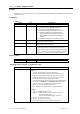


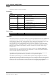


Connector Type Possible Values of signal and qualifierX
Front Panel Trigger Out The value of signal is interpreted as a signal offset in mV.
E.g. signal = -500 offsets the output signal by –500 mV. The
accepted range of signal is [-2500,2500], i.e. ± 2.5 V with a
resolution of ~20 mV.
The value of qualifier1 controls if the trigger output is
resynchronized to the clock or maintains a precise timing relation to
the trigger input.
qualifier1= 0 (default): Non-resynchronized
qualifier1= 1 : Resynchronized to sampling clock
PXI Bus 10 MHz 0 = Disable
1 = Enable
Replaces the internal 10 MHz reference clock with the 10 MHz
clock on the PXI rear panel connector.
PXI Bus Star Trigger 0 = Disable
1 = Use PXI Bus Star Trigger as Trigger Input
2 = Use PXI Bus Star Trigger for Trigger Output
Note: When using this connector as Trigger Input, you also must
set the trigger source in sourcePattern in the function
AcqrsD1_configTrigClass to External Trigger2!
Discussion
ControlIO connectors are front panel IO connectors for special purpose control functions of the digitizer.
Typical examples are user-controlled acquisition control (start/stop/skip) or control output signals such as
‘acquisition ready’ or ‘trigger ready’.
The connector numbers are limited to the allowed values. To find out which connectors are supported by a
given module, use the query function
AcqrsD1_getControlIO.
The variable signal specifies the (programmable) use of the specified connector.
In order to set I/O A as a ‘Enable Trigger’ input and the I/O B as a 10 MHz reference output, use the
function calls
AcqrsD1_configControlIO(instrID, 1, 6, 0, 0.0);
AcqrsD1_configControlIO(instrID, 2, 19, 0, 0.0);
In order to obtain a signal offset of +1.5 V on the Trigger Output, use the call
AcqrsD1_configControlIO(instrID, 9, 1500, 0, 0.0);
Programmer’s Reference Manual Page 73 of 210