
User manual
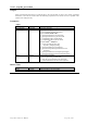

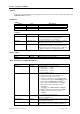

In this table
‘X’ means that the functionality is available depending on the option but independent of the model,
'8' means that the functionality is available for 8-bit Digitizers and AP units in the digitizer mode,
'10' means that it is available for the 10-bit Digitizers,
'12' means that it is available for the 12-bit Digitizers.
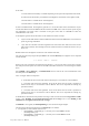
It must be remembered that 12-bit digitizers generate 12 or 13-bit data which will be transferred as 2 bytes
with the data shifted so that the MSB of the data becomes the MSB of the 16-bit word, thus preserving the
sign information. The vGain value is therefore not the gain of the ADC in volts/LSB but rather the
volts/LSB of the 16-bit word.
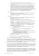
10-bit digitizers generate 12-bit data which can be transferred in either of 2 ways
• 2 bytes with the data shifted so that the MSB of the data becomes the MSB of the 16-bit word, thus
preserving the sign information
• 1 byte with the 8-bit data of the most significant bits of the ADC value. Here the lowest two bits
will be lost (truncated). The advantage is that the amount of data to be transferred has been cut by a
factor of 2.
Real64 readout of 10-bit digitizers is based on 16-bit transfer of the data,
The value in Volts of any integer data point data in the returned dataArray for a digitizer can be computed
with the formula:
V = vGain * data – vOffset
Except in the case of Analyzers, the data points for dataType = 3 are in Volts and no conversion is needed.
For Analyzers the data points are in units of the LSB of the ADC and must be converted using the formula
above.
For readMode = 0 and dataType ≤ 1, indexFirstPoint must be used for the correct identification of the
first data point in the dataArray.
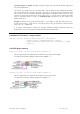
The 3 "averaged" modes correspond to:
2 – 24-bit data read as such into either Int32 32-bit integers or converted into volts for Real64,
5 – 16-bit data read of the least significant 16 bits of the 24-bit sum. The result is presented in
either an Int16 array or converted into volts for Real 64. The user is responsible for treating any
potential overflows,
6 – 16-bit data read of the most significant 16 bits of the 24-bit sum. The result is presented in
either an Int16 array or converted into volts for Real 64. The user is responsible for treating any
potential overflows.
It should also be noted that the interpretation of averager results was discussed in the Programmer’s Guide
section 3.10.4, Reading an Averaged Waveform from an Averager and 3.10.5, Reading a RT
Add/Subtract Averaged Waveform from an Averager.
If readMode is set to gated, the nbrSamplesInSeg is set to the sum of the gate lengths.
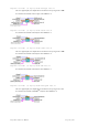
The rules for the allocation of memory for the dataArray are as follows:
For digitizers (or other modules used as such)
o with readMode = 0 and dataType = 0, the array size in bytes must be at least
(nbrSamplesInSeg+32).
o with readMode = 0 and dataType = 1, the array size in words must be at least
(nbrSamplesInSeg+32).
Programmer’s Reference Manual Page 166 of 210