
User manual
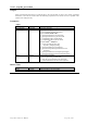


nbrSamplesInSeg ViInt32 Requested number of samples, may assume 1 to the
actual number of samples.
segmentOffset ViInt32 ONLY used for readMode = 1 in DIGITIZERS:
Requested offset, in number of samples, between
adjacent segments in the destination buffer dataArray.
Must be ≥ nbrSamplesInSeg
dataArraySize ViInt32 Number of bytes in the user-allocated dataArray. Used
for verification / protection.
segDescArraySize ViInt32 Number of bytes in the user-allocated segDescArray.
Used for verification / protection.
flags ViInt32 As used for DIGITIZERS
Bit Function
0
LSB
If set the first data point is at a fixed number
of points with respect to the resynchronized
trigger, otherwise it is before delayTime after
the Trigger
1 If set the lookup table (if any) will not be used
to translate the data, otherwise it will be.
3 If set the memory image will be transferred in
an image read but no segment re-ordering will
be done, otherwise it will be.
For Averagers if Bit 2 is set the accumulated data will
not be reset after being read, otherwise it will be.
AcqirisDataTypes.h contains AqReadDataFlags an
enum which encodes the above values.
reserved ViInt32 Reserved for future use, set to 0.
reserved2 ViReal64 Reserved for future use, set to 0.
reserved3 ViReal64 Reserved for future use, set to 0.
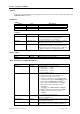
Segment Descriptor for Normal Waveforms (readMode = 0,1,3) in AqSegmentDescriptor
Name Type Description
horPos ViReal64 Horizontal position of first data point.
timeStampLo
timeStampHi
ViUInt32
ViUInt32
Low and high part of the 64-bit trigger timestamp. See
discussion below.
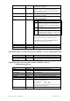
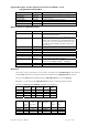
Segment Descriptor for Averaged Waveforms (readMode = 2,5,6) in
AqSegmentDescriptorAvg
Name Type Description
horPos ViReal64 Horizontal position of first data point.
timeStampLo
timeStampHi
ViUInt32
ViUInt32
Low and high part of the 64-bit trigger timestamp. See
discussion below.
actualTriggersInSeg ViUInt32 Number of actual triggers acquired in this segment
avgOvfl ViInt32 Acquisition overflow. See discussion below.
avgStatus ViInt32 Average depth and status. See discussion below.
avgMax ViInt32 Max value in the sequence. See discussion below.
flags ViUInt32 The lowest four bits contain the hardware marker
values. The correspondence is
Bit 0 (LSB) = P1, Bit 1 = P2
Bit 2 = I/O A Bit 3 = I/O B
The marker is set at the last trigger, in the first round of
the acquisition of the segment.
reserved ViInt32 Reserved for future use
Programmer’s Reference Manual Page 164 of 210