
User manual


The External Clock function is available in AcqirisLive only when using the control panel in Transient Recorder
Mode. The input frequency should be keyed into the clock frequency selector (outlined in red) on the control panel.
Then the appropriate sampling frequency must be selected in order for the proper timebase to be displayed on the
waveform display window. The time window displayed can be manipulated by allocating more or less memory to the
acquisition.
The External 10 MHz Reference in AcqirisLive is designed to work either in Oscilloscope Mode or in Transient
Recorder Mode. The timebase and sample rate for waveform capture is fully selectable when using the external
reference, just as it is when using the digitizer’s own internal reference clock.
4.9. Additional Waveform Information
The Options menu also includes possibilities to obtain additional information about the waveform. In both cases
described below the display will be updated after each acquisition.
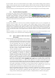
The “Show Segment Timestamps” option shows a display like the one below:
It gives you the information needed to better understand the trigger times of the
individual segments of an acquisition. By definition the first trigger of an
acquisition occurs at t
1
=0.0. There are two columns for each digitizer. For the n’th
row, the first column contains the difference t
n
– t
n-1
and the second column
contains t
n
. The top line contains the average value of the t
n
in the left column and
the standard deviation of the t
n
in the right one. The times are in ps.
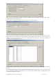
The “Show Parameters” option activates a display of pulse parameters for each
active channel. Inactive channels will have parameter values of 0.0. The parameters
will be calculated in a model in which the distribution of measured voltages has
two distinct peaks. If this condition is not satisfied the results will be unrelia
ble.
4.10. Display Features
Display features in the Options menu include items for
• turning the waveform display off (by de-selecting “Display Waveforms”),
• overlaying segments of a sequence,
• connecting displayed data points,
• modifying the display refresh rate,
• displaying the internal temperature of the currently selected module
4.11. Command Line Switches
When starting the AcqirisLive application, the executable's name in the command line can be followed by one or
more switches to change the running conditions.
Syntax
The syntax of the command line is the following:
path\AcqirisLive.exe options
where options are chosen from the following list
[-a][-b][-B][-c][-d][-h][-i][-l][-m][-n][-p][-s][t][-v][-x]
Available Switches
List of available switches:
-a start in Averager mode
-b Buffer size for large waveforms
-B Number of bank for SAR mode
-c no initial calibration
-d use DMA for data transfers (default)
User Manual: Agilent Acqiris 10-bit Digitizers Page 36 of 43