
User manual


3.4.5. Window Trigger
The digitizers implement a Window trigger. Two trigger level thresholds are used to define the desired range. The
trigger can then be chosen to occur either when the signal exits or enters the window range. This mode can be
thought of as the appropriate OR of two edge triggers of opposite slope.
3.4.6. HF Trigger
The digitizers implement an HF trigger that allows triggers to be reliably accepted at rates above ∼ 1 GHz. In this
mode, triggers occur on every fourth positive edge. The window trigger mode is not available.
3.4.7. Spike Stretcher
The trigger circuit also has a Spike Stretcher mode which ensures that even very short pulses are capable of
generating triggers. This mode is useful if the time interval during which the trigger signal satisfies the threshold
condition is less than 0.5 ns and the trigger frequency is less than 10 MHz. The trigger slope is positive in this mode.
3.4.8. Multi-source Trigger
The 10-bit digitizer family permits triggers that require a pattern condition including combinations of the trigger
channels and the external trigger. The trigger condition defined above, on each of the inputs, defines the
TRUE/FALSE state of each input. These states can be logically combined with AND, OR, NAND, or NOR to define
the overall trigger condition. Potential triggers can then occur on the FALSE to TRUE transitions of the combined
signal.
There is a small (~ns) delay between the times at which two simultaneous inputs arrive at the logical element that
defines the overall trigger condition. If necessary, this must be corrected for by cable delay on the external input; the
delay will depend on the overall configuration and therefore must be determined by the user.
3.4.9. Pre- and Post-Trigger Delay
To increase trigger flexibility a pre- or post-trigger delay can be applied to the trigger position.
The amount of pre-trigger delay can be adjusted between 0 and 100% of the acquisition time window (i.e. sampling
interval x number of samples), whereas the post-trigger delay can be adjusted within the time interval corresponding
to [0, 2
35
– 1 samples].
Pre- or post-trigger delays are just different aspects of the same trigger positioning parameter:
• The condition of 100% pre-trigger indicates that all data points are acquired prior to the trigger, i.e. the trigger
point is at the end of the acquired waveform.
• The condition of 0% pre-trigger (which is identical to a post-trigger of 0) indicates that all data points are
acquired immediately after the trigger, i.e. the trigger point is at the beginning of the acquired waveform.
• The condition of a non-zero post-trigger delay indicates that the data points are acquired after the trigger occurs,
at a time that corresponds to the post-trigger delay, i.e. the trigger point is before the acquired waveform.
The digitizer hardware accepts pre- and post-trigger adjustments in increments of 16 samples. By definition post-
trigger settings are a positive number and pre-trigger settings are a negative number.
Thus it is only natural that the software drivers treat pre- and post-trigger delays as a single parameter in seconds that
can vary between –nbrSamples * samplingInterval (100% pre-trigger) and +maxPostTrigSamples * samplingInterval
(max post-trigger). Since the Acqiris software drivers provide very accurate trigger position information upon
waveform readout, the accepted resolution of the user-requested pre-/post-trigger delay is much better than 16
samples. For more details, refer to the Programmer’s Guide.
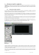
3.4.10. Trigger Status
The front panel includes a tri-color LED indicator to show the status of the trigger. When the LED is green it
indicates the trigger is armed and waiting for a valid trigger to occur. Red indicates that the trigger has occurred, the
acquisition is complete and the data is waiting to be readout. The user can override the default functions and program
the LED color in an application-specific manner.
User Manual: Agilent Acqiris 10-bit Digitizers Page 22 of 43