
User manual


3.3.7. Combining channels
The DC152, DC252, and DC282 digitizers offer the possibility of combining the converters (and their memories)
from two or four channels to analyze a single input channel. With this feature the maximum sampling rate and the
maximum amount of acquisition memory can be doubled or quadrupled if all of the input channels are not of
immediate interest.
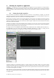
3.3.8. Data Readout
The DC222, DC252, and DC282 digitizers are capable of handling 64-bit 66 MHz readout. Such operation requires a
single board computer or a cPCI interface + PC supporting such functionality. All devices in the crate must be
capable of 66 MHz readout. The crate may also have to be set so as to allow this mode; this means M66EN must be
open and V(I/O) should be 3.3 V. Acqiris CC103, CC105, and CC108 crates have toggle switches to select such use.
This cannot be done in larger crates such as the Acqiris CC121. The actual transfer speed obtainable will depend on
many other system characteristics.
3.4. Trigger
Normally the trigger settings applied to the digitizer are used to determine the time at which the device will stop
acquiring data. They are also capable of a ‘Start on Trigger’ mode of acquisition (see the Programmer’s Guide for
further details). The various trigger settings are outlined below.
3.4.1. Trigger Source
The trigger source can be a signal applied to either an Input Channel (internal triggering) or the External Trigger
Input. A standardized trigger in signal can also be routed via the PXI Bus Star Trigger line. Because of their high
bandwidth HF front ends do not allow internal triggering.
The digitizers provide a separate front panel input that can be used as an External Trigger Input. The External Input
provides a fully functional trigger circuit with selectable coupling, level and slope as for the Internal Triggering
source. The external trigger has a fixed 50 Ω termination impedance. It allows optional BW limiter selections of 20,
200, or 700 MHz. The external trigger circuit has diode protection against overload. In all 50 Ω cases a ±5 V limit on
trigger signals should be respected, although somewhat higher voltages for short time periods will not damage the
unit.
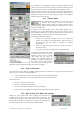
3.4.2. Trigger Coupling
Trigger coupling is used to select the coupling mode applied to the input of the trigger circuitry. Modes available
include AC LF Reject and DC. The AC LF Reject mode couples signals capacitively and removes the input signal's
DC component and signals below 50 Hz. DC mode allows all signal components to be passed through to the trigger
circuit. The HF Reject mode removes signal components above 50 KHz.
3.4.3. Trigger Level
The trigger level specifies the voltage at which the selected trigger source will produce a valid trigger. The trigger
level is defined as a set voltage. Using the internal trigger, the level is set with respect to the midpoint voltage (V
m
= –
Offset voltage)
of the digitizer’s vertical scale. Internal trigger level settings (expressed in %) must be within V
m
±
0.5 FS, where FS is the channel Full Scale. All trigger circuits have sensitivity levels that must be exceeded in order
for reliable triggering to occur.
The digitizers allow the user to choose the external trigger Full Scale from the set of values 0.5, 1.0, 2.0 or 5.0 V.
The external trigger level can then be set to values in the range ± 0.5 FS.
The digitizers will trigger on signals with a peak-peak amplitude > 15% FS from DC to their bandwidth limit.
3.4.4. Edge Trigger Slope
The trigger slope defines which one of the two possible transitions will be used to initiate the trigger when it passes
through the specified trigger level. Positive slope indicates that the signal is transitioning from a lower voltage to a
higher voltage. Negative slope indicates the signal is transitioning from a higher voltage to a lower voltage.
User Manual: Agilent Acqiris 10-bit Digitizers Page 21 of 43