USER MANUAL AGILENT ACQIRIS 10-BIT DIGITIZERS Models covered: DC122 / DC152 U1062A DC222 / DC252 / DC282 U1065A
Manual Part Number U1092-90004 Edition B-RevG, June 2008 The information in this document is subject to change without notice and may not be construed in any way as a commitment by Agilent Technologies, Inc. While Agilent makes every effort to ensure the accuracy and contents of the document it assumes no responsibility for any errors that may appear. All software described in the document is furnished under license. The software may only be used and copied in accordance with the terms of license.
CONTENTS 1. OUT OF THE BOX........................................................................................................................... 5 1.1. Message to the User ..................................................................................................................... 5 1.2. Using this Manual ........................................................................................................................ 5 1.3. Conventions Used in This Manual ................................
3.4.2. Trigger Coupling............................................................................................................ 21 3.4.3. Trigger Level.................................................................................................................. 21 3.4.4. Edge Trigger Slope......................................................................................................... 21 3.4.5. Window Trigger ...................................................................................
1. Out of the Box 1.1. Message to the User Congratulations on having purchased an Agilent Technologies Acqiris data conversion product. Acqiris digitizers are high-speed data acquisition modules designed for capturing high frequency electronic signals. To get the most out of the products we recommend that you read this manual carefully. We trust the product you have purchased will meet with your expectations and provide you with a high quality solution to your data conversion applications. 1.2.
1.4. Model Names Agilent Technologies Inc. acquired Acqiris SA and its product lines in December 2006. Use the tables below to cross reference the legacy model name and new Agilent numbers Agilent Model Number U1062A U1062A U1065A U1065A U1065A 1.5. Acqiris Model Name DC122 DC152 DC222 DC252 DC282 Disclaimer and Safety The 10-bit DC Series CompactPCI/PXI digitizers have been designed to operate inside a CompactPCI/PXI crate. The crate provides the modules with all needed power.
After carefully unpacking all items, inspect each to ensure there are no signs of visible damage. Also check that all the components received match those listed on the enclosed packing list. Agilent cannot accept responsibility for missing items unless we are notified promptly of any discrepancies. If any items are found to be missing or are received in a damaged condition please contact the Agilent service center or your local supplier immediately.
LabVIEW RT: A driver is available for National Instruments LabVIEW RT version 7.1 or higher. The VISA driver must be version 3.0 or higher. MATLAB: The MEX interface can be used with MathWorks MATLAB 7.3 or a newer version. Visual BASIC: The interface files and examples are available for Microsoft Visual Basic versions 5 or 6 and the interface files only for .NET. Tornado: The example files are useable with Wind River Tornado 2.2.1 1.11.
2. Installation This chapter describes how to install the Acqiris hardware and software for Windows 2000/XP, Linux, National Instruments LabVIEW RT, Linux, or Wind River VxWorks. NOTE: For a first time installation we strongly recommend installing the software before inserting the hardware into the PC. 2.1.
The PCI-8570/PXI-8570 User's Manual (Rev. 1.00) section 2.4 contains the software installation instructions. These should be executed before allowing the hardware installation process to look for the driver. If you have an AdLink CD Version 2004A4 or later you can use it; if not you should download the latest driver from the WEB site (http://www.adlinktech.com/). You can then continue with the Hardware Installation. A reboot will then be necessary.
If MATLAB is installed on your machine, you will be asked to point the installer to the MATLAB root directory. You should do this if you want the installer to modify the standard startup.m file to incorporate the Acqiris adaptor. In the Installation Folder window you will give the name of the root directory of the Acqiris software installation. If User Manuals (30 MB) and Firmware (40 MB) are loaded more space than indicated here will be required on the drive. For the case of a Tornado 2.
To install the device driver you have to rename the kernel module whose name matches the version of your kernel to a name without this version number. Compiling the kernel module All files needed to compile a new kernel mode driver are in AcqirisLinux/linuxdriverpci for Linux kernels 2.4, or AcqirisLinux/linux2.6driverpci for Linux kernels 2.6. To compile the driver, the header files of the Linux kernel need to be installed.
You can check that the driver is loaded properly with lsmod. /sbin/lsmod | grep acqrsPCI If lsmod does not report a module named acqrsPCI, then the kernel module is not loaded into the kernel. Read the section below. You can check that a device node has been created. ls -l /dev/acqrsPCI If the device node /dev/acqrsPCI is not present on your system, the Acqiris Software will not be able to access the device. Read more in the section below.
2.4. 1. Installing the Hardware Turn off the power of the PC and the crate in the case of a CompactPCI module. CAUTION: For PCI modules the PC may have to be unplugged to ensure that the PCI bus has no power available. However, CompactPCI crates can be left plugged in since this ensures proper grounding. CAUTION: Touch the antistatic package to a grounded object before removing the card from the package. Electrostatic discharge can damage the card. 2.
NOTE: In some systems an application program (such as AcqirisLive) will not yet work correctly at this point. One additional boot cycle may be needed if this is the first time that a hardware board is being installed. 2.6. LabVIEW RT During program development you can choose whether you use LabVIEW or LabVIEW RT compatible libraries by switching the version present in National Instruments\LabVIEW m.n\instr.lib\.
3. Product Description 3.1. Overview Simplified Block Diagram once for each channel Signal Input 10-bit 10- bit Input Signal Amplifier SH + ADC DEMUX 256K Acq Mem 50 Ohms TIMEBASE trigger Input Trigger Signal Amplifier TRIGGER circuit Thr DAC 50 Ohms Cal DAC Card Controller PCI Interface PCI Bus The 10-bit DC series products are CompactPCI/PXI compliant and require an appropriate CompactPCI crate.
3.2. Channel Input The 10-bit digitizer family can be configured with a variety of front-end mezzanine boards offering different capabilities. The currently available front end options are detailed below: Front End Option Standard Impedance Bandwidth Guaranteed (typical) / Risetime BW Limiter selections FS Voltage Ranges Maximum Offset / Max. Voltage 50 Ω 2 GHz 20, 200, 700 MHz 0.05 – 5.0 V ±5V 950 MHz ( 1 GHz) 0.35 ns 20, 200, 700 MHz 0.05 – 5.0 V HighImpedance (300 MHz) 1.
3.2.5. Bandwidth and Rise Time The bandwidth specification indicates the frequency at which an input signal will be attenuated by 3 dB (approximately 30% loss of amplitude). The bandwidth also affects the minimum rise and fall times that can be passed through the front-end electronics. A pulse with a very sharp edge will be observed to have a minimum rise time (τmin) determined by the front-end electronics.
3.3. Data Acquisition The table below summarizes the characteristics discussed in the sections that follow: Model Agilent # DC122 Max. Sampling Rate Max. CONVERTERS PER CHANNEL/ CHANNELS Default Memory Samples/ channel Maximum Optional Memory Maximum Segments Samples/ channel 4 GS/s 1/1 512K 512M 125K 4 GS/s 2/2 256K 256M 125K 8 GS/s 1/1 1024K 1G 125K 8 GS/s 2/2 512K 512M 125K 8 GS/s 4/4 256K 256M 125K U1062A DC152 U1062A DC222 U1065A DC252 U1065A DC282 U1065A 3.3.1.
The Single Acquisition mode is the normal operation of most digitizer products. In this mode an acquisition consists of a waveform recorded with a single trigger. The user selects the sampling rate and acquisition memory size and sets the number of segments to 1 (default value). The Sequence Acquisition mode allows the capture and storage of consecutive “single” waveforms.
3.3.7. Combining channels The DC152, DC252, and DC282 digitizers offer the possibility of combining the converters (and their memories) from two or four channels to analyze a single input channel. With this feature the maximum sampling rate and the maximum amount of acquisition memory can be doubled or quadrupled if all of the input channels are not of immediate interest. 3.3.8. Data Readout The DC222, DC252, and DC282 digitizers are capable of handling 64-bit 66 MHz readout.
3.4.5. Window Trigger The digitizers implement a Window trigger. Two trigger level thresholds are used to define the desired range. The trigger can then be chosen to occur either when the signal exits or enters the window range. This mode can be thought of as the appropriate OR of two edge triggers of opposite slope. 3.4.6. HF Trigger The digitizers implement an HF trigger that allows triggers to be reliably accepted at rates above ∼ 1 GHz. In this mode, triggers occur on every fourth positive edge.
3.5. External Clock and Reference For applications where the user wants to replace the internal clock of the digitizer and drive the ADC with an external source, either an External Clock or an External Reference signal can be used. The Clock or Reference signals can be entered into the digitizer by the dedicated MMCX. In addition, the PXI Bus 10 MHz system clock signal (PXI_CLK10) can be used as the reference. The External Clock must be continuously present for use by these digitizers.
AS bus 2 is intended to connect modules of the same type, i.e. of the same model number, although some exceptions to this rule might be possible. If modules with the same model number, but different memory length options, are connected only the shortest memory length can be used. The AS bus 2 connector is located on the front panel of each module. Bridges are used to connect adjacent modules for synchronization. An AS bus 2 multi-instrument is activated through software by a function call.
3.10. Electrical, Environmental and Physical Specifications 3.10.1. Electrical PCI Rev. Max. Power Consumption (W) Current Requirements (A) Model +12 V +5 V +3.3 V -12 V DC122 Default Memory 2.2 31.9 0.11 3.5 3.5 0.01 DC122 Optional Memory 2.2 41 0.11 3.5 6.3 0.01 DC152 Default Memory 2.2 32.9 0.11 3.7 3.5 0.01 DC152 Optional Memory 2.2 42.1 0.11 3.7 6.1 0.01 DC2x2 Default Memory 2.2 61.6 0.1 6.7 7.2 0.03 DC2x2 Optional Memory 2.2 80 0.1 6.7 12.5 0.
3.10.2. Environmental and Physical The modules have a Declaration of Conformity according to ISO/IEC Guide 22 and EN45014 and CE Marks of Compliance. The front panels of the CompactPCI modules are in compliance with the IEEE 1101.10 standard. Operating Temperature 0° to 40°C The above values are for the ambient temperature of the room (or equivalent) where the CompactPCI crate is located. The temperature as measured on the board may well be significantly higher.
4. Running the AcqirisLive Application AcqirisLive is an application to control and demonstrate the capabilities of Acqiris digitizers on a single machine. AcqirisMAQS is a more advanced application offering many interesting possibilities for the control of acquisition systems in a single or multi-machine environment. Ask your sales representative or Agilent Acqiris Support for more information. 4.1.
4.2. DSO TR Control Panel and Functions 4.2.1. Control Panel Mode In AcqirisLive there are two control panel modes available, Oscilloscope Mode and Transient Recorder Mode. The choice of mode is entirely determined by the preference of the user. Both modes provide the same set of functional capabilities but display the settings slightly differently.
Oscilloscope Mode Transient Recorder Mode 4.2.2. Displaying Multiple Traces If multi-channel modules, or several single channel modules, are installed on the PCI bus, multiple waveform displays, one from each installed channel, are overlaid on the display. The current channel is selected by clicking on the channel name within the upper portion of the control panel. The vertical settings of the current channel and the timebase and trigger of the correspondent digitizer are then indicated.
As an alternative to controlling the channels to be displayed from the control panel you can also control them by selecting the desired channels from the list of channel gains shown at the right hand side of the display window. Pressing the Finder button at the top of the control panel will identify the module associated with the current channel. When the finder button is depressed, the LED on the front panel lights up yellow on the digitizer module with the current channel. 4.2.3.
1. Clicking on the white numeric display of the voltage scale will show a pop-up list. Select the desired gain setting with the mouse pointer. 2. Clicking on the Decrement / Increment icons will step the voltage scale up or down to the next level for each click of the mouse. 3. Clicking Max / Min will toggle to the least sensitive gain setting or to the most sensitive gain setting. The input Coupling can be set for AC or DC.
armed and ready to acquire data. In Single and Normal modes the display will only be updated after each active digitizer has received a trigger. Stop will stop the acquisition and hold the latest complete acquisition on the display. Single mode is used in order to capture one event at the first valid trigger. It freezes the acquisition in the digitizer’s memory, and on the display, until the user requests another acquisition.
• Select the desired time per division setting (timebase panel): the fastest sampling rate for the current digitizer, compatible with the maximum number of samples, will be selected and applied to all digitizers in the system. Any digitizer not capable to satisfy that sampling rate will run at its closest setting. Finally, note that the sampling rate menu (visible in Transient Recorder Mode) contains the sampling rate capability of all digitizers currently in use.
the zoom window. There are two modes available, the Live Display, or the Persistence Display. When persistence display is selected, all points drawn to the display windows remain on while new points are added from subsequent acquisitions. This mode is particularly suited for examining the jitter on an edge of a periodic signal as shown in the image below. To clear the display in persistence display mode, press the “Clear” button that appears on the main display window. 4.3.
The Binary file format selection provides the fastest storage performance and generates the smallest files on the hard drive. Binary files can be subsequently converted to either Raw ADC values or to Amplitude values using the Data Format Conversion utility provided with AcqirisLive. Selecting the “Write files at end option” acquires all waveforms into memory first, before converting to the selected format and writing the data to disk. This option allows for faster data capture times.
The External Clock function is available in AcqirisLive only when using the control panel in Transient Recorder Mode. The input frequency should be keyed into the clock frequency selector (outlined in red) on the control panel. Then the appropriate sampling frequency must be selected in order for the proper timebase to be displayed on the waveform display window. The time window displayed can be manipulated by allocating more or less memory to the acquisition.
-h high priority process (default) -i use acquisition interrupts -l low priority process -m medium priority process -n no DMA for data transfers -p Use acquisition polling -r start in Transient Recorder (digitizer) mode -s simulation mode -t temperature update off -v show acquisition state -x disable automatic multi-instruments Operation Mode Acqiris averagers can be operated in Averager Mode or in standard Digitizer Mode.
Please note that switching DMA data transfer mode off precludes the use of acquisition interrupts. The –i switch will therefore be ignored when –n is used. Process Priority When the program checks for an event from the operating system (e.g. to react to user input), it can put itself to sleep for a specified period of time. This gives other applications more processor time, but limits the performance of AcqirisLive in terms of maximum acquisition rate.
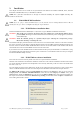
5. Running the GeoMapper Application 5.1. Who needs a Geographical Map of Modules The GeoMapper application gives the user the possibility of telling the Acqiris driver crucial details of the physical position of modules when this information cannot be deduced directly. It allows the driver to correctly adjust trigger and clock delays between the different modules of an AS bus 2 multi-Instrument and arrange the modules in an intuitive order.
Selecting a row will cause all of the LED's of modules in that Bus to be turned on RED. This should make it easy to identify which crate the modules are in. The third step is to specify the number of slots in each crate. This is shown below: The 4th step consists of arranging the modules of each crate into the correct order. The menu shown below is one in which all of this work has been done for the modules of a fully populated CC121. Selecting a position will cause a module to have its red LED turned on.
6.
7.
8.