
User`s manual
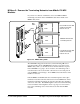
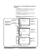
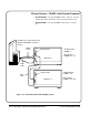
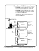
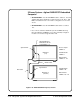

3-Frame System - Agilent RADI-EPC7 Embedded
Computer
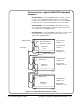
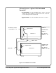
• MAINFRAME 1: Set the VXI-MXI module to address 1. It does
not have to be an instrument identifier address. Set other VXI
modules in the mainframe to addresses below 128. Note: The EPC7
is installed in slots 1 and 2 and configured as a non-slot 0 device.
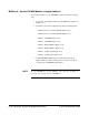
• MAINFRAME 2: Set the VXI-MXI module address to address
128. Set all other VXI modules to addresses between 129 and 159
(do not duplicate the VXI-MXI address).
• MAINFRAME 3: Set the VXI-MXI module address to 160. Set all
other VXI modules to addresses between 161 and 191 (do not
duplicate the VXI-MXI address).
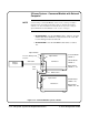
VXI-MXI Module
LADDR = 128
Other Modules
LADDRs 129 - 159
EPC7 Computer
LADDR = 0
VXI-MXI Module
LADDR = 1
Other Modules
LADDRs 2 - 127
Agilent E1482
Agilent E1482
Mainframe 1
(root)
Mainframe 3
(extender)
Agilent RADI-EPC7
Embedded Computer
MXIbus Cable
INTX Cable
VXI-MXI Module
LADDR = 160
Other Modules
LADDRs 161 - 191
Agilent E1482
Mainframe 2
(extender)
Figure 3-17. EPC7 Embedded Controller, 3-Frame
C-Size Configuration Guide Set Up the System for Multiple Mainframes 3-17