
User`s manual

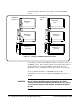
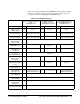

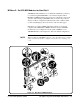

The following table summarizes the VXI-MXI module’s switch and jumper
settings for slot 0 and non-slot 0 operation. Continue with this procedure
for specific details on configuring the VXI-MXI module.
Root or Extender Mainframe
with
VXI-MXI in Slot 0
Root Mainframe with
E1406A, or V743
and VXI-MXI not in Slot 0
Root Mainframe with
Agilent RADI-EPC7, and
VXI-MXI in Slot 0
Switch or Jumper Fig # Description Fig # Description Fig # Description
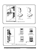
Switches S1, S8
(VXIbus Slot 0)
3-4a Slot 0 3-4b Non-slot 0 3-4a Slot 0
MXIbus Terminating
Resistor Networks
3-10 Remove unless last
device in the daisy chain
3-10 Installed 3-10 Remove unless last
device in the daisy chain
INTX Terminating
Resistor Networks
3-10 Remove unless last
device in the daisy chain
3-10 Installed 3-10 Remove unless last
device in the daisy chain
Jumpers W1, W2, W3,
W4, W5 (VMEbus
Request Level)
Level 3 requester
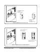
Jumper W6
(VME BTO Level)
3-5a
VME timeout 100 µsec
3-5b VME timeout
200 µsec
3-5b
VME timeout 200 µsec
Jumper W7
(VME BTO Chain
Position)
3-7a 1 extender, slot 0 3-7b 1 extender, non-slot 0 3-7a 1 extender, slot 0
Switch S3
(Interlocked Arbitration)
Interlocked
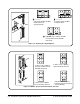
Switch S4
(MXIbus System
Controller)
3-6a Not MXIbus controller 3-6b MXIbus controller 3-6b MXIbus controller
Jumper W8
(MXI Controller Timeout
Level)
3-9d MXIbus timeout disabled 3-9a MXIbus timeout
100 µsec
3-9a MXIbus timeout
100 µsec
Switch S2
(MXIbus Fairness)
Fairness enabled
Jumpers W9, W10
(CLK10 Source)
3-8a On-board 10 MHz
VXI-MXI installed in slot 0
3-8c Do not source CLK10 3-8a On-board 10 MHz
VXI-MXI installed in slot 0
Switches W1, W2, W3
(CLK10 Mapping)
CLK10 mapping disabled
Switch S6
(Ext Clk SMB)
Output external clock
Switch S5
(Trigger Input
Termination)
Trigger 50Ω terminated
Switch S7
(Front Panel Pushbutton)
SYSRESET* asserted
Table 3-1. Configuration Settings.
C-Size Configuration Guide Set Up the System for Multiple Mainframes 3-3