
User`s manual

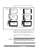

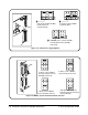

The following figure illustrates some typical 2- and 3-frame MXIbus
systems:
Notice that we’ve given each mainframe a number to identify its location in
the MXIbus system. These numbers will be used throughout this chapter to
describe different locations in the MXIbus system. Notice also that
Mainframe 1 (the root mainframe) contains the system resource manager.
For more detailed information on VXI-MXI extender module
configurations, refer to the Agilent E1482A VXI-MXI Bus Extender User’s
Manual.
CAUTION Do not install a VXI-MXI module configured for Slot 0 into
another slot without reconfiguring it for Non-Slot 0 use. Doing
so can result in damage to the module, the VXIbus backplane,
or both.
VXI-MXI as
Slot 0
Mainframe 3
(extender)
Mainframe 2
(extender)
Mainframe 3
(extender)
Mainframe 2
(extender)
Mainframe 1
(root)
Mainframe 1
(root)
VXI-MXI as
Non-Slot 0
Figure 3-1. Looking at a Multiple Mainframe System
3-2 Set Up the System for Multiple Mainframes C-Size Configuration Guide