
User`s manual


#
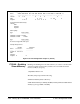
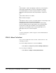
# This database contains the mapping of VXI devices to Interrupt lines.
# Note that not all VXI devices need to use interrupt lines and that
# not all interrupt lines need to be assigned. However, no interrupt
# line that is allocated in this file can be allocated in the ’vmedevices’
# file.
#
# The format of this files is as follows:
#
# line handler interruptors ...
#
# All fields are <tab> or <space> seperated. All values can be #expressed in
# decimal, or hex. The ’line’ field is the interrupt line
# being allocated. There can be at most one line for each interrupt
# line. The handler field is the logical address of the interrupt handler
# for this line (not that only one handler can be assigned for any
# given line). The interruptors field is a list of logical addresses of
# interrupters that can use this interrupt line.
#
1 2
As shown, interrupt line 1 will be assigned to the Command Module at
logical address 2.
V743-5 : Where To Go Next
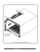
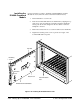
Once you have installed the V743 controller, continue with one of the
following procedures:
If you have multiple mainframes connected via MXIbus:
• "Procedure 3: Set Up Your System for Multiple Mainframes"
If you are using one mainframe:
• "Procedure 4: Configure and Install Instruments"
2-48 Setting Up an Embedded V743 Controller C-Size Configuration Guide