
User`s manual


V743-2B : Setting
the Command
Module Servant
Area
Notice the following when setting the Command Module servant area.
• For the Command Module to be the commander of a register-based
module, the register-based module’s logical address must fall within
the Command Module’s servant area. The servant area of the
Command Module is determined as:
Servant area = (logical address + 1) through (logical address +
servant area switch setting)
• The logical address plus the Command Module’s servant area cannot
exceed 255. Therefore, set the servant area based on the logical
addresses of the register-based modules in your system.
For example, if the Command Module’s logical address is 1 and its
servant area switch is set to 100, the Command Module would be the
commander for all modules with logical addresses from 2 through
101.
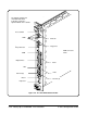
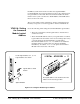
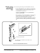
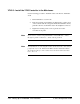
Servant area 255 is shown.
The servant area is the decimal sum of the switches in the
closed (1) position.
E1406A
Servant Area switch location
Figure 2-33. Setting the E1406A Servant Area
C-Size Configuration Guide Setting Up an Embedded V743 Controller 2-39