
User`s manual


The V743 Logical
Address and
Servant Area
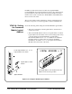
The following pertains to the V743 logical address and servant area:
• The V743 controller has a logical address of 0 and a servant area of
255. These values are stored in software and cannot be changed.
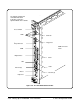
• With a logical address of 0, the V743 is the VXI system’s resource
manager. It is recommended that the V743 be installed in mainframe
slot 0 so that it also functions as the system’s slot 0 device.
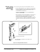
• With its logical address set at 0 and its servant area set at 255, the
V743 controller is the system’s top level commander. However, a
commander can be a servant to another commander thus forming a
hierarchial system. Servants in the servant area of the "lower-level"
commander are controlled by the lower-level commander.
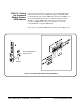
• The V743 should be the commander of the system’s message-based
modules (including other commanders). This enables the
message-based modules to be programmed at higher speeds across
the VXIbus backplane. A commander such as the Agilent E1406A
Command Module should be the commander for the system’s
Agilent Technologies register-based modules. This enables the
register-based modules to be programmed with SCPI commands via
the Command Module.
V743-2 : Set Up the Agilent E1406A Command Module
Note If an Agilent E1406A Command Module is part of your system, continue
with Step V743-2. Otherwise, proceed to step V743-3.
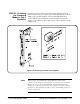
When an embedded controller such as the Agilent E1497A V743/64 or
Agilent E1498A V743/100 and a Agilent E1406A Command Module are
part of your VXIbus system, you must configure the Command Module for
use with the V743. This includes:
• setting the Command Module logical address so that it is a servant to
the V743
• setting the Command Module servant area so that it is the
commander of the system’s Agilent Technologies register-based
modules
• setting the Command Module primary GPIB address
• disabling the Command Module’s slot 0 and system controller
capability
C-Size Configuration Guide Setting Up an Embedded V743 Controller 2-37