
User`s manual
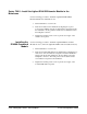

Assigning Interrupt
Lines
There are seven backplane interrupt lines. These lines are assigned to
devices by the resource manager during the system’s power-on sequence.
When the HP Series 700/E1489I is the resource manager, it assigns line 1 to
itself, and assigns lines 2, 3, 4, ... to other interrupt handlers in the system.
In systems containing a Series 700/E1489I (resource manager) and an
Agilent E1406A Command Module, the Series 700/E1489I will assign the
Command Module interrupt line 2 - if the Command Module has the next
lowest logical address.
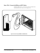
Agilent Technologies’ register-based modules are factory-set to interrupt
line 1. This setting is selected on some modules by a finger-moveable
jumper; on others the jumper is soldered onto the module. When line 1 is
not assigned to the Command Module, you must either assign line 1, or
move the jumpers on its register-based servants to the corresponding lines.
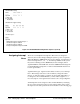
An Interrupt line can be assigned to the Command Module by modifying
the "irq.cf" file used by the Series resource manager. The location of this
file depends on the Series platform shown in the table on the following page.
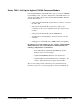
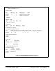
VXI-MXI IRQ Routing:
Name 1 2 3 4 5 6 7
-------- - - - - - - -
hpvximxi I I I I I I I
I - MXI->VXI
O - VXI->MXI
* - Not Routed
VXI-MXI TTL Trigger Routing:
Name 0 1 2 3 4 5 6 7
--------- - - - - - - - -
hpvximxi I I I I I I I I
I - MXI -> VXI
O - VXI -> MXI
* - Not Routed
VXI-MXI Registers:
Name
--------
hpvximxi
laddr window register: 0x3f00 range: 0-1
a24 window register: disabled
a32 window register: disabled
Interrupt Configuration Register: 0xffffffff
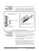
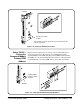
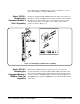
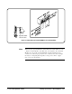
Figure 2-21. E1489I/E2093B Configuration Sequence (Cont’d)
2-32 Setting Up a Series 700 Computer C-Size Configuration Guide