
User`s manual

Series 700-2A :
Setting the
Command Module
Logical Address
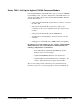
Notice the following when setting the Command Module logical address.
• The Command Module has a factory-set logical address of 0. Since
logical address 0 is the address of the resource manager (the Agilent
E1489I card in the Series 700), you must change the Command
Module’s logical address. Recommended addresses are 1, 2, or 3.
Series 700-2B :
Setting the
Command Module
Servant Area
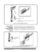
Notice the following when setting the Command Module servant area.
• For the Command Module to be the commander of a register-based
module, the register-based module’s logical address must fall within
the Command Module’s servant area. The servant area of the
Command Module is determined as:
Servant area = (logical address + 1) through (logical address +
servant area switch setting)
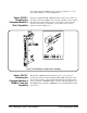
• The logical address plus the Command Module’s servant area cannot
exceed 255. Therefore, set the servant area based on the logical
addresses of the register-based modules in your system.
For example, if the Command Module’s logical address is 1 and its
servant area switch is set to 100, the Command Module would be the
commander for all modules with logical addresses from 2 through
101.
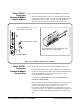
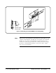
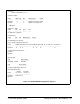
Set the logical address to 1, 2, or 3.
Logical address 0 is shown.
The logical address is the decimal sum of the
switches in the closed (1) position.
Agilent E1406A
Logical address switch
Figure 2-15. Setting the E1406A Logical Address
2-24 Setting Up a Series 700 Computer C-Size Configuration Guide