
User`s manual

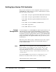

Testing ROM
Testing 512K Bytes RAM
Passed
Testing CPU
1. CPU Self Test Passed
GPIB address: 09
Talk/Listen
Command Module ladd = 0
Command Module servant area = 255
Command Module VME bus timeout -- DISABLED
Searching for static devices in mainframe 0
SC device at ladd 0 in slot 0
2 Searching for static devices on interconnect bus 1
Searching for dynamic devices in mainframe 0
Searching for pseudo devices
Configuring Commander / Servant hierarchy
3 ladd = 0, cmdr ladd = -1
Validating Commander / Servant hierarchy
Mapping A24 Memory
4 ladd 0, offset = 00200000H, size = 131072 Bytes
Mapping A32 memory
Configuring VME interrupts
VME interrupt line 1 assigned to ladd 0, handler ID 1
VME interrupt line 2 - no handler assigned
VME interrupt line 3 - no handler assigned
5. VME interrupt line 4 - no handler assigned
VME interrupt line 5 - no handler assigned
VME interrupt line 6 - no handler assigned
VME interrupt line 7 - no handler assigned
SYSTEM INSTALLED AT SECONDARY ADDR 0
6. SYSTEM instrument started
File System memory: 40131
File System Started
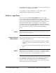
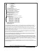
1. The Agilent E1406A operating system performs a series of self-tests and clears its volatile RAM. The Command
Module’s GPIB address, logical address, servant area, and VME (data transfer) bus timer functionality are reported. You
must disable the VME bus timer when Agilent E1482A VXI-MXI mainframe extender modules are part of your system.
2. For each mainframe, the resource manager locates all statically configured modules, locates and configures all
dynamically configurable modules, and then locates pseudo devices such as IBASIC. The VXI-MXI extender outward and
inward logical address windows are then opened.
3. The resource manager establishes the VXIbus system’s commander/servant hierarchies based on the commander’s
servant area and the servant’s logical address. The Command Module in this configuration is the top-level commander,
and as such, is not a servant to another commander (cmdr ladd = -1).
4. The resource manager allocates A24 and A32 addresses for those modules’ memory requirements. Note that the offset
is specified in hexadecimal and the size is specified in bytes. A24 and A32 address space is opened up to modules
accessed through the VXI-MXI mainframe extender modules.
5. The resource manager allocates interrupt lines to all interrupt handlers in the system. Agilent register-based modules
have their interrupt line jumper set to ’1’ at the factory. In systems with multiple Command Modules the other interrupt lines
are assigned. Modules controlled by those Command Modules must have their jumpers moved accordingly. Interrupt line
’1’ is enabled to route interrupts OUT from mainframe 137 to the handler in mainframe 0. Interrupt line ’1’ is enabled to
route interrupts IN to the interrupt handler in mainframe 0 (VXIbus extender 2). All other interrupt routing lines are disabled
since there are no other interrupt handlers.
6. The resource manager identifies the secondary GPIB addresses in the system, starts the system instrument (i.e.
Command Module), issues the Begin Normal Operation (BNO) command to its message based servants and opens GPIB
access to those modules.
Figure 2-12. The Agilent E1406A Power-on Sequence
2-14 Setting Up the E1406 Command Module C-Size Configuration Guide