
User`s manual


Command Module’s power-on and configuration sequence, and function as
a front panel to your VXIbus C-Size system.
See Appendix A, "Terms and Definitions," for information on the
Command Module’s RS-232 interface configuration
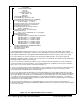
E1406-10 : Apply Power
Check that the Agilent E1406A Flash ROMS switch is in the "Run"
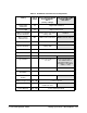
position and then turn on the VXI mainframe. An example of the E1406A’s
power-on and configuration sequence is shown in Figure 2-12. This
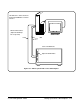
sequence can be monitored on an RS-232 terminal or printer connected to
the Command Module’s RS-232 serial interface port (see "RS-232
Connections" on page 2- 12). Pressing CTRL S on the terminal keyboard
pauses the sequence. Pressing CTRL Q allows the sequence to resume. Note
that once the sequence is paused, it remains paused until CTRL Q is
pressed.
NOTE If a serial terminal or printer is not available, the program in Procedure 6
can be used to check your system.
Configuration and
Start-Up Errors
If the Command Module fails its self test, the "Failed" annunciator lights up
on the faceplate. Should this occur:
• turn the mainframe off, remove the Command Module, check the
configuration switches (i.e. logical address, slot 0/system controller
enable).
• if necessary, call your nearest Agilent Technologies sales and service
office.
NOTE When using the Command Module for the first time or when the mainframe
has not been turned on for at least one week, leave the mainframe on for at
least 15 hours to fully charge the Command Module’s battery.
If a configuration or start-up error such as an invalid address or failed self
test occurs, the error is reported in the power-on and configuration
sequence. A list of the configuration and start-up error messages and their
causes can be found at the end of this guide.
C-Size Configuration Guide Setting Up the E1406 Command Module 2-13