
User`s manual

Setting Up the Agilent E1406A Command Module
This procedure explains how to set up and install an Agilent 75000 Series C
VXIbus system with an external computer (Personal Computer or
Workstation) connected to the Agilent E1406A Command Module via
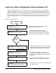
GPIB. This procedure consists of the following steps:
• E1406-1 : Set the Command Module as Resource Manager
• E1406-2 : Set the Command Module as Slot 0 Device
• E1406-3 : Set the Clock Source
• E1406-4 : Set the Bus Request Level
• E1406-5 : Configure the Command Module’s Shared RAM
• E1406-6 : Set the Command Module’s Servant Area
• E1406-7 : Set the Command Module’s Primary GPIB Address
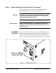
• E1406-8 : Install the Command Module into the Mainframe
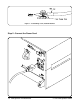
• E1406-9 : Connect Interface Cables
• E1406-10 : Apply Power
• E1406-11 : Where To Go Next
If you need information on terms used in this manual, see Appendix A,
"Terms and Definitions."
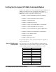
Agilent E1406A Default
Configuration
The following shows how the Agilent E1406A Command Module is
configured at the factory. These settings are appropriate for most VXI
systems. A quick verification of these settings will save you time.
Switch Setting
Logical Address 0
Servant Area 255
GPIB Address 9
VME Bus Timer (BTO) Enabled
Slot 0 Enabled
VME System Controller Enabled
CLK10 Source Internal
Bus Request Level 3
Shared RAM Enabled (256 kB)
2-2 Setting Up the E1406 Command Module C-Size Configuration Guide