
User`s manual
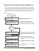

Procedure 2:
Set Up the VXI System Controller
The controller to VXI mainframe interface determines how commands and
data will flow between the controller and the mainframe. This procedure is
divided into five sections according to the controller used:
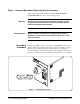
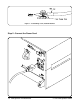
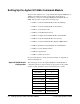
• Setting Up the Agilent E1406A Command Module - This section
covers the setup of the Agilent E1406A Command Module
connected to an external controller using the General Purpose
Interface Bus (GPIB). See Page 2-2
• Setting Up a Series 700 Controller - This section covers the setup
of an HP 9000 Series 700 external controller with an Agilent E1489I
MXIbus Controller Interface Card connected to an Agilent E1482
VXI-MXI Bus Extender Module in slot 0. See Page 2-18
• Setting Up an Embedded V743 Controller - This section covers
the setup of an Agilent E1497A/98A Embedded V743 controller
with the VXIbus as the communication path. See Page 2-35
• Setting Up an Embedded Agilent RADI-EPC7 486 Computer -
This section covers the setup of an Agilent RADI-EPC7 Embedded
Computer with the VXIbus as the communication path.
See Page 2-49
WARNING SHOCK HAZARD. Only service-trained personnel who are aware
of the hazards involved should install, remove, or configure the
system. Before you perform any procedures in this guide,
disconnect AC power and field wiring from the mainframe.
CAUTION STATIC ELECTRICITY. Static electricity is a major cause of
component failure. To prevent damage to the electrical
components in the mainframe and plug-in modules, observe
anti-static techniques whenever handling a module.
2-1 Set Up the VXI System Controller C-Size Configuration Guide