
User`s manual


• The logical address window of the root mainframe must be a valid
window (valid starting address and size), and include all of the
modules in all of the extender mainframes connected to it.
• No module in one mainframe can be in another mainframe’s logical
address window. Therefore, the logical addresses within a
mainframe should be set such that as small a window as possible is
allocated.
• The logical address window of an extender mainframe must include
all modules in that mainframe. The VXI-MXI extender module,
however, does not have to be within the window, but must not be
within the window of another mainframe.
See the Agilent E1482B VXI-MXI Bus Extender User’s Manual for
additional information on determining the Logical Address Window.
What is an
Instrument
Identifier?
Instruments comprised of Agilent Technologies message-based and
register-based modules which are servants to the Agilent E1406/05
Command Module are created according to the following rules:
• Each instrument must have one plug-in module assigned as an
Instrument Identifier. The Instrument Identifier is the module with
its logical address set to a multiple of 8, such as 8, 16, or 24.
• The Instrument Identifier is the lowest logical address in the
instrument. The Command Module maps the Instrument Identifier
logical address to a secondary GPIB address by dividing the logical
address by 8. Thus, a logical address of 8 maps to a secondary GPIB
address of 1; logical address 16 maps to secondary address 2; logical
address 24 maps to 3 and so on.
• If an instrument consists of a single module, then its logical address
must be set to an Instrument Identifier address (multiple of 8).
What are Virtual
Instruments?
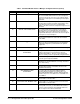
• An instrument consisting of multiple modules is called a virtual
instrument. The modules of the virtual instrument must be assigned
successive logical addresses beginning with the address of the
Instrument Identifier. For example, to create a scanning multimeter
virtual instrument which consists of a multimeter and two
multiplexers, the logical addresses could be set to:
24 (multimeter)
25 (1st multiplexer)
26 (2nd multiplexer)
C-Size Configuration Guide Terms and Definitions A-9