
User`s manual


What is the
Command Module’s
10 MHz Clock
Source?
One of the slot 0 resources supplied by the Command Module is the
10 MHz system clock: CLK10. This clock is distributed to every slot along
the VXIbus backplane. The clock may be an internal signal generated by
the Command Module, or an external signal supplied to the backplane via
the SMB faceplate connector on the Command Module. The following
guidelines will help you set the system clock configuration:
• The Agilent E1406 Command Module’s CLK10 source is set to
"Internal" at the factory.
• The initial accuracy of the internal 10 MHz ECL clock is
± 50 ppm. The duty cycle is 50% ±5%.
• The CLK10 source can be routed to external devices using the ’Clk
Out’ SMB connector.
• If an external clock is selected, the signal is input to the Command
Module through the ’Clk In’ SMB connector.
• Disabling the slot 0 and (VME) System Controller functions
removes the internal system clock or external clock from the VXIbus
backplane. However, the clock from either source is still present at
the ’Clk Out’ SMB connector.
What is the
Command Module’s
Bus Request Level?
The bus request level is a priority at which the Agilent E1406 Command
Module can request the use of the Data Transfer Bus. The following
guidelines will help you set the level:
• There are four bus request levels to choose from: 0 - 3. Bus request
level 3 has the highest priority; bus request level 0 has the lowest
priority.
• The Command Module’s bus request level switch is set to 3 at the
factory. In most VXIbus systems and configurations, it is not
necessary to change this setting.
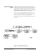
Data Transfer Bus
Arbitration
In a VXIbus system, the Data Transfer Bus (DTB) is used for addressing
and data transfer. As a result, many instruments in a typical VXIbus system
request the use of the bus. Arbitration of the DTB is done by the slot 0
module, using a Fair Requester protocol. This protocol requires that once a
module has requested and has been granted the bus, it may not request the
bus again until 30 ns after the bus request line is released. Although the bus
grant signal is daisy-chained from module to module, the 30 ns delay
prevents a module in a lower slot from continually being granted the bus.
The Command Module, even though it may be the slot 0 module, must also
request the bus in the same manner as any other module.
C-Size Configuration Guide Terms and Definitions A-3