
User`s manual


DEBUG7 : Check the Instrument’s Arm-Trigger Subsystem
All SCPI instruments follow an Arm-Trigger model that is described in
most operating manuals and in the "Beginner’s Guide to SCPI" document.
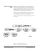
This model has both required and optional levels:
IDLE required
ARM:LAYer<x> optional
ARM:LAYer<2> optional
ARM:LAYer1 optional
INITIATED required
TRIGger optional
sequence operation required
The Arm-Trigger subsystem starts with the IDLE state which occurs at
power-on, following ABORT or *RST, or after a previous Arm-Trigger
cycle that has completed.
Command configuration occurs when the instrument is in the IDLE state.
After the instrument has been configured (including its ARM and TRIGger
functions), the INITiate command is executed which moves the instrument
to the INITIATED state. Once initiated, reception of the appropriate arm
and trigger signals start the sequence operation.
Since each instrument may implement different ARM layers, TRIGger
sources, etc., refer to the operating manual for information on the exact
ARM/TRIGger sequence used.
An example ARM/TRIGger sequence follows:
/* Program a Function Generator to output 100 cycles of a waveform
whenever a signal is applied to its "Aux In" port */
/* Arm source = Aux In port source */
ARM:STAR:LAY2:SOUR EXT;
/* Infinite number of Aux In arms */
ARM:STAR:LAY2:COUN INF;
/* 100 cycles */
ARM:STAR:LAY1:COUN 1E2
/* Initiate the waveform (trigger source internal) */
INIT
C-Size Configuration Guide System Programming and Debugging 6-11