
User`s manual


Configuration and
Start-Up Errors
If the Command Module fails its self test, the "Failed" annunciator lights up
on the faceplate. Should this occur:
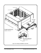
• Turn the mainframe off, remove the Command Module, check the
configuration switches (i.e. logical address, slot 0/system controller
enable).
• If it still fails, turn the mainframe off, remove all other installed
modules. Apply power, and if the Command Module passes its self
test, add the other plug-in modules one at a time - cycling power
each time.
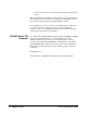
SYSTEM INSTALLED AT SECONDARY ADDR 0
VOLTMTR INSTALLED AT SECONDARY ADDR 3
MBinstr INSTALLED AT SECONDARY ADDR 17
MBinstr INSTALLED AT SECONDARY ADDR 18
IBASIC INSTALLED AT SECONDARY ADDR 30
IBASIC memory: 115232
6. SYSTEM instrument started
File System memory: 40131
File System Started
BNO issued to ladd 136, BNO response = FFFE
Opening GPIB/IBASIC access for message based device at sec addr 17
BNO issued to ladd 144, BNO response = FFFE
Opening GPIB/IBASIC access for message based device at sec addr 18
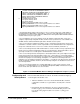
1. The Agilent E1406 operating system performs a series of self-tests and clears its volatile RAM. The
Command Module’s GPIB address, logical address, servant area, and VME (data transfer) bus timer
functionality are reported. You must disable the VME bus timer when Agilent E1482A VXI-MXI mainframe
extender modules are part of your system.
2. For each mainframe, the resource manager locates all statically configured modules, locates and
configures all dynamically configurable modules, and then locates pseudo devices such as IBASIC. The
VXI-MXI extender outward and inward logical address windows are then opened.
3. The resource manager establishes the VXIbus system’s commander/servant hierarchies based on the
commander’s servant area and the servant’s logical address.The Command Module in this configuration is
the top-level commander, and as such, is not a servant to another commander (cmdr ladd = -1).
4. The resource manager allocates A24 and A32 addresses for those modules’ memory requirements. Note
that the offset is specified in hexadecimal and the size is specified in bytes. A24 and A32 address space is
opened up to modules accessed through the VXI-MXI mainframe extender modules.
5. The resource manager allocates interrupt lines to all interrupt handlers in the system. Agilent Technologies
register-based modules have their interrupt line jumper set to ’1’ at the factory. In systems with multiple
Command Modules the other interrupt lines are assigned. Modules controlled by those Command Modules
must have their jumpers moved accordingly. Interrupt line ’1’ is enabled to route interrupts OUT from
mainframe 137 to the handler in mainframe 0. Interrupt line ’1’ is enabled to route interrupts IN to the interrupt
handler in mainframe 0 (VXIbus extender 2). All other interrupt routing lines are disabled since there are no
other interrupt handlers.
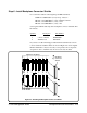
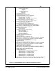
6. The resource manager identifies the secondary GPIB addresses in the system, starts the system
instrument (i.e. Command Module), issues the Begin Normal Operation (BNO) command to its message
based servants and opens GPIB access to those modules.
Figure 5-1. Command Module Resource Manager Configuration Sequence (Cont’d)
C-Size Configuration Guide Applying Power 5-3