
Specifications

6
Power Switch
• On/Standby switch on front with lighted indicator.
• May be switched to On/Standby remotely via diagnostic
connector (E8404A only).
• May be switched to On/Standby via SCPI command
(E8404A only).
+5VSTDBY
(Power may be provided by the user to the +5VSTDBY bus on the VXI backplane.)
Current: 1 A max
Voltage range: 5.25 V max., 4.875 V min.
Connector: Pins 8 and 21 of the diagnostic
connector
(Power may be provided by the user to operate the enhanced monitor in the
absence of line power.)
External +5VSTDBY (E8404A only)
Current: 500 mA min. (needed for enhanced
monitor operation),1.5 A max. on
connector.
Voltage range: 5.25 V max., 4.875 V min.
Connector: Rear panel
Power Supply Protection
All voltages are protected from over-temperature, over-
voltage, over-current, short-to-ground and short-to-other-
output. Protection mode is full shutdown. Recovery occurs
when the fault condition is removed and power on/standby
is cycled.
Airflow and Cooling
Airflow is routed into the rear and exhausted out the upper
sides of the mainframe. Allow 50 mm of clearance for
proper air flow.
Fan Speed
(Cooling Mode, High or Variable, switchable on the front panel. Controls both
module impeller and power supply fan.)
High fan speed mode: Full airflow all the time
Variable fan speed mode: Fan speed increments through 8
discrete speeds as a function of
ambient, module, and power supply
temperatures.
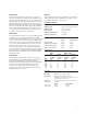
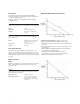
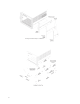
Airflow
VXI-8 Specification Draft 2.0. Fixture revision 1.7.
• VXI-8 Standard Modules installed in all other slots.
• Performance shown for Worst Slot (slot 1) and Best Slot
(slot 10).
• Front-to-Rear Variance 13% worst case. Typically 10%-12%
in most slots.
• Fans on Full Speed. Minimum airflow is approximately
50% with fans on Variable Speed.
• Air Filter Kit not installed. Airflow is reduced
approximately 10% with clean air filters installed.
• Measurements taken at 1,500 m altitude.
E8401A/03A/04A Cooling Specification Charts