
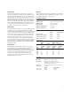
Specifications

3
At-a-Glance Confidence in Operation
The front panel indicator lights on all three VXI mainframes
give immediate visual indication that the power supply
voltages are operating within the VXI Specification, the
temperatures are within limit, and that the fans are
operational. Backplane activity and SYSFAIL indicators are
also provided.
The system can be reset easily from the front panel of all
three mainframes, providing reset even when the Slot 0 is
inaccessible due to cabling.
The diagnostic connector, conveniently located on the front
of all three mainframes, provides connection for remote
monitoring of power supply voltages, power supply and
reference temperatures, and fans function. This connector
also allows remote on/standby, access to +5VSTDBY,
ACFAIL, and SYSRESET. The connector’s functionality is a
superset of the functionality on the E1401B mainframe,
allowing software and hardware compatibility with existing
applications. Up to 1 A of +5VSTDBY may be provided by
the user through the connector. Up to 1 A each of +5 V and
+12 V are available for external applications through the
connector.
E8404A Enhanced Monitoring
• VXIbus or RS-232 communication
• Three temperature sensors per slot
• Cooling control
• Power supply voltage and current
• Stripcharts and histograms for easy diagnostics
• Audible warnings of over-limit conditions
• History queue
• VXI
plug&play
WIN Framework driver
• English, French, German, and Spanish language support
State-of-the-art enhanced monitoring is provided on the
E8404A VXI mainframe. The enhanced monitor board plugs
into the backplane from the rear of the mainframe; it does
not occupy a slot in the mainframe or tie up a MODID line.
The E8404A enhanced monitoring is message based,
allowing easy communication with the mainframe for the
user over RS-232 or through the VXIbus. SCPI commands
are used to address the mainframe. A VXI
plug&play
WIN
Framework driver is provided.
On the E8404A, temperature monitoring includes module
exhaust temperatures at three points on every slot, power
supply temperature and ambient temperature.
Measurements at the front, center and rear of every slot
provide an accurate assessment of the temperature
fluctuations over a variety of cards, whose hottest
components may vary in position. Display screens are
provided for overall temperature map, temperature limits
set, stripcharts and histograms of each slot.
E8404A temperature monitoring is also used for cooling
control. Both the absolute temperature of the slots and the
temperature rise over ambient temperature are measured.
Cooling speed is increased when either an absolute
temperature or a temperature rise approaches its respective
limit. The user may adjust these control limit ranges
programmatically.
Speeds of the E8404A power supply fans and the impeller
are displayed as a percentage of full speed and as the
number of rotations per minute.
All seven voltages, +5VSTDBY and the optional user-
supplied external 5 V power are measured on the E8404A.
Current monitoring is provided and power is calculated for
each power supply voltage. Overview display screens are
provided for all these data; more detailed information is
also available in stripcharts and histograms. These values
are visible on the display and are available through the VXI
and RS-232 interfaces.
On the E8404A, warning alarms occur when a temperature
is over limit, power supply voltages are out of VXI
specification, when current or total power exceeds user set
limits, or for certain user-defined conditions. A beeper
provides audible warnings; it is enabled or disabled through
a SCPI command or through the front panel keys.
The enhanced monitor includes a maintenance timer. This
timer may be set, queried, and reset by the user for support
of scheduled maintenance activities, such as cleaning the
optional air filter.
The enhanced monitor may operate independently of line
power by using an external +5 V power supply. When line
power goes down, communication with the enhanced
monitor is possible via the RS-232 interface.
With the E8404A, a remote power-on signal is available via
the diagnostic connector’s "remote on signal" or through a
SCPI command.
Localization enables the user to select English, French,
German, or Spanish languages on the display for ease of
operation worldwide.