
User`s manual


Resetting the Module
A reset signal is provided to initialize the backplane interface circuit and
your own custom-designed circuitry to a known state. Both hardware and
software resets are implemented for your convenience.
Hardware Reset The backplane SYSRESET* line drives both the hardware reset (HRESET*)
and the software reset (CRESET*) user access points low (0) on the breadboard
module. HRESET* goes to the clear inputs of U22 and U23, which drives all
of the Control Register outputs (access points CTL2 - CTL15) low (0).
Software Reset Control Register output bit CTL0 is used for the software reset. If you write a
"1" to bit CTL0, the CRESET* access point on the module is driven low (0) by
U4C. You can use CRESET* any way you choose in your custom circuitry.
CAUTION
The VXI:RESET <logical_addr> command writes "1’s" to all
device dependent bits in the Control Register. Your custom
designed circuitry should tolerate this and not malfunction during
reset. This is defined in the VXIbus Specification Observation C.2.9.
Detecting Errors
The breadboard module implements the following error/fail circuitry:
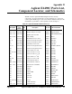
• The Status Register implements bit SR2 as a self-test "Passed/Failed"
bit (see Table 3-1 on page 51). If SR2 (PASSED access point) is set
low (0), indicating your custom circuit self test either failed or is
currently still executing and the SYSFAIL INHBT bit (CTL1 output
of the Control Register) has been set low (0), then the module sets
the backplane SYSFAIL* line true through U4B and U5D. If either
SYSFAIL INHBT or the "PASSED" bit are set high, SYSFAIL*
remains false.
• The ACFAIL* line has been stubbed onto the module from
backplane connector P1 (pin B3) and is available as a user access
point for your convenience.
Chapter 3 Using the Agilent E1490C 59