
User`s manual


Using Interrupts
The breadboard module can be configured to generate an interrupt to the
interrupt handler when service is required.
Configuring for
Interrupts
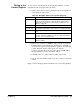
To configure the module to generate interrupts, you must first assign an
interrupt priority level to the module. Levels 1-7 are available, with level 7
being the highest level. Jumper J1 selects the interrupt REQUEST level
(interrupt generated on the Agilent E1490C breadboard) and Jumper J2
selects the interrupt ACKNOWLEDGE level (interrupt passed through the
VXI backplane to the Agilent E1490C). Both jumpers must be set to the
same level.
Generating
Interrupt Requests
To generate the interrupt request and accept the interrupt acknowledgement
from the interrupt handler, you must implement the following actions:
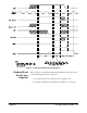
• You must provide the interrupt request from your custom circuits by
setting the IRQ access point low (0) when the interrupt is to occur.
Interrupts are edge triggered.
• If more than one module in the mainframe has the same interrupter
priority level, to ensure that this module reacts to its own interrupt
acknowledge, position the breadboard module in the closest slot to
the right of the interrupt handler.
• If you do not implement the interrupter capability, you must ensure
that the daisy-chained IACKIN* signal is passed to IACKOUT*
either on your module or by bypassing the slot entirely using jumpers.
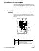
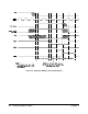
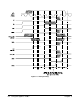
• Your system controller and/or interrupt handler must react to the
signal timing in the PAL (U9) for the IRQ and DTACK state
machines as shown in Figure 3-5.
• The circuitry provided implements a read operation for only the
lower eight bits of status/ID during the interrupt acknowledge cycle,
using PIACK* to enable buffer U10. If you want to use the upper
eight bits also, you must provide an additional buffer to the internal
data bus that is enabled by PIACK* true and DS1* true.
• For testing purposes only, move Jumper J3 from the NORMAL
position to the TEST position. In the TEST position, an interrupt can
be generated by writing a "1" to Control Register bit 2. In the
NORMAL Position, Control Register bit 2 can be used as a user
signal, CTL2.
Chapter 3 Using the Agilent E1490C 57