
User`s manual


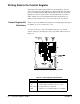

Writing Data to the Control Register
The breadboard module contains circuitry for a Control Register. You can
write to this register from the backplane over data lines D0 - D15. The data is
passed to the internal data bus DB0 - DB15 and then clocked into the Control
Register for use by the custom circuitry on the breadboard at access points
CTL2 - CTL15. Do not tie anything here that cannot tolerate having a "1"
written to it with software reset or do not use software reset. See page 59.
Control Register Bit
Definitions
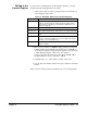
Table 3-3 shows the definitions preassigned to Control Register data bits per
the VXIbus Specification (Section C.2.1.1.2).
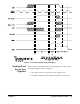
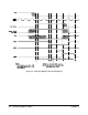
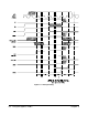
You may connect any of the Control Register outputs to your custom
circuitry using the Control Register access points (CR2 - CR15) shown in
Figure 3-3.
Table 3-3. Control Register Bit Definitions
Data Bit(s) Definitions
CR0 (1 = Reset the module, User defines reset actions)
CR1 (1 = inhibit setting of SYSFAIL*; if Reset = 1, safe)
CR2 - CR14 Device Dependent (user assignable)
CR15 (1 = Enable access to A24/A32 Registers; 0 = Disable)
Figure 3-3. Control Register Access Points
54 Using the Agilent E1490C Chapter 3