
User`s manual


Reading the Status
Register
For example, assume you need to use up to 16-bits of the Status Register,
including latching the data in both halves of the register. To latch your
status data and then read the 16-bit contents of the Status Register onto the
backplane, you must implement the following signal and control lines:
1. Address the module correctly by placing the data shown in Table 3-2
on the backplane address lines:
2. This is a read operation, so READ* must remain false (1) to provide
the second half of the U24/U25 enable function (WRITE*).
3. Set IACK* false (1) to enable address equality detector U18.
4. Set both data strobes DS0* and DS1* true (0) to indicate a 16-bit data
transfer.
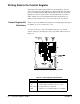
Table 3-2. Backplane Address Lines (Status Register)
Line(s) Data Required
Lines A1 - A3 Must be set low/high/low (010) to select the BASE + 4 enable line.
BASE + 4 provides one half of the enable function for line drivers U7/U8
(See Table 2-2 on page 34).
Lines A4, A5 Must both be low (0) to enable 3-to-8 line decoder U21.
Lines A6 - A13 Must equal the logical address of the module as set on DIP switch SP1.
Lines A14, A15 Must always be set high (1) to access the upper 16K of address space.
Lines AM0 - AM5 Must be set to either hexadecimal 29 (10 1001) or hexadecimal 2D
(10 1101). Refer to the
VMEbus Specification (Table 2-3) and the
VXIbus Specification (Rule C.2.10).
Line LWORD* Must always be set false (1) since this is a D16 device (short word
transfer = 16-bits).
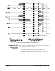
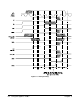
Figure 3-2 shows timing required for the PAL (U9) control and signal lines.
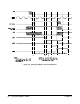
Figure 3-1. Status Register Access Points
52 Using the Agilent E1490C Chapter 3