
User`s manual
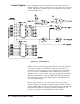
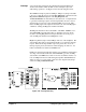


Since this is a write operation, LATCH* goes true for one clock cycle as part of
the data transfer cycle. With both BASE + 8 and LATCH* set low, the output
of U101A briefly goes high, clocking the relay selection bit pattern onto the
outputs of U105 and U106, which are not yet enabled. The outputs of U105 -
U108 are enabled by the following path. The output of U101A is also applied
through U101B to U103A, a monostable multivibrator. When LATCH*
returns to its normally high state after one clock cycle, U101A output goes low
and the U101B output goes high, triggering U103A. U103A produces a
low-going output pulse at pin 4 (Q*) that enables the outputs of U105 - U108.
The relay configuration bit pattern is then applied through U109 and U110
to the relay SET lines. U109 and U110 invert the bit pattern and provide
current sinks for the selected SET relay coils. A "1" at the output of
U105/U106 energizes a SET relay coil while a "0" is ignored. The outputs
of U105 and U106 are also applied to U107 and U108 which place the
inverse of the relay selection bit pattern on the RESET lines of the relays
through U111 and U112. U111 and U112 provide current sinks for the
RESET relay coils. Since the inverse state is applied to U111 and U112,
those relays not SET are RESET.
Notifying the
Controller
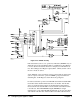
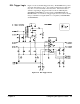
For this application, only one bit is needed for the Status Register. Pin 13
(Q) output of U103A is connected directly to the SR7 bit line on TP191.
This bit is normally always kept low and is used as the module "busy" bit
when set high.
When U103A produces its low-going output pulse at pin 4 (Q*), it also
produces a high-going output pulse at pin 13 (Q). The duration of these two
pulses is controlled by the values of C101 and R101, which for this application
is about 11 ms (slightly longer than the settling time of the relays).
The Q pulse sets the "busy" bit high in the Status Register while the relays are
settling. If the system controller polls the module while the relays are still
settling (to see if the relays are configured yet), it will see the "busy" indication
and can do something else while it is waiting for the relays to settle.
If the user wants the module to notify the interrupt handler when the relays are
settled, note that the trailing edge of the Q* output pulse from U103 will also
clock U104. This produces a high at IRQ. When the PAL (U1) senses the high
at IRQ, it starts the IRQ state machine, notifying the interrupt handler via
IRQ1* on the backplane that (in this case) the relays are settled out.
The system controller can then either poll the Status Register to check the
"busy" bit, or it can assume the bit is cleared and proceed. To reset U104
and remove the high on IRQ, the system controller must drive CRESET*
true while PIACK* is true as part of the interrupt acknowledge cycle.
U102C and U102D accomplish the reset.
48 Configuring the Agilent E1490C Chapter 2