
User`s manual
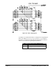

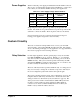

Power Supplies Table 2-12 lists the power supply pins available from the P1 and P2 connectors.
The + 5 and – 5.2 Vdc interface supplies are fused and filtered (– 2 Vdc is used
but not fused). You should fuse and filter all other power supplies used.
Table 2-12. Power Supply Voltage and Pin Numbers
Voltage P1 Connector Pin
Numbers
Voltage P2 Connector Pin
Numbers
+5Vdc A32, B32, C32 –5.2Vdc A7, A13, A19, C4, C19
+5Vstdby B31 +24Vdc C31
+12 Vdc C31 –24Vdc C32
–12Vdc A31 –2Vdc A2, C13
All ground pins connect together; no ground loops are present in the
module. The shields are not grounded but access points are provided at the
standoffs to connect the shields. The front panel connects to the shields.
Unconnected heavy traces are provided at the circuit board edges for
bussing power supplies and ground to custom circuitry.
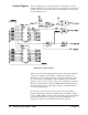
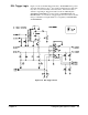
Custom Circuitry
This section contains an example which shows one way you can install
custom circuitry on the Agilent E1490C breadboard module. The example
shows a 16-channel general purpose relay application. See Appendix B and
the fold-out on page 49 for the following discussion.
Relay Selection For this sample application, Form C general purpose relays are used that
have SET and RESET modes of operation. Writing a "1" to a particular
relay driver (U105 or U106) SETs the relay and writing a "0" to the driver
RESETs the relay. The system controller specifies which relays are SET
and which are RESET by writing an entire 16-bit word of 1’s and 0’s to the
module to identify the desired state of all the relays.
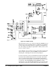
The state of all relays must be specified simultaneously. To change just one
relay, it is necessary to change the one bit that corresponds to that relay in
the stored configuration pattern and send the entire pattern again.
The system controller places the 16-bit "relay configuration" word onto the
backplane data bus (D0 - D15) and transfers it to the breadboard module
during a normal write data transfer cycle (as described on page 35). The
data is passed to the module’s internal data bus (DB0 - DB15) when the
module is correctly addressed. In this application, DB0 - DB15 are
connected to two drivers (U105 and U106) which are clocked by the
BASE + 8 (low) enable line address selection.
Chapter 2 Configuring the Agilent E1490C 47