
User`s manual
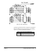
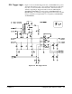


User Access Points The breadboard module contains traces (stubs) for accessing many of the
signal lines on backplane connectors P1 and P2. Table 2-10 shows the
signal lines that are brought onto the module but not implemented. They are
available as signal access points for your custom circuits.
Table 2-10. User Access Points (Stubs)
Signal Lines Description
ACFAIL* AC Input Power Fail
LBUSA0-11 Daisy-chained Local Bus A
LBUSC0-11 Daisy-chained Local Bus C
SERCLK Synchronizes data transmission on the VMEbus
SERDAT* Used for VMEbus data transmission
SUMBUS Analog Summing Node
TTLTRG 0*-7* Intermodule Communication Lines (TTL Level)
+5VSTDBY When implemented in the VXI mainframe, supplies
+5 Vdc to devices needing battery backup.
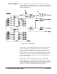
Table 2-11 shows all of the implemented signal lines available as access
points, either as inputs from the backplane to your own custom circuitry, or
as outputs to the backplane from your custom circuits.
Table 2-11. User Access Points (Implemented Signals)
Signal Lines Description
BA1 - BA5 Buffered Backplane Address Lines A1 - A5
ID* ID Register Enable Line
DEVTYPE* Device Type Register Enable Line
STATUS* Status and Control Registers Enable Line
REG0* User Assignable Enable Line
REG1* User Assignable Enable Line
REG2* User Assignable Enable Line
REG3* User Assignable Enable Line
REG4* User Assignable Enable Line
CRESET* Card Reset, software (CTL0) or hardware (SYSRESET*)
CTL2 - CTL15 Control Register Output Lines
DB0 - DB15 Breadboard Module Internal Data Bus Lines
DTACK Data Transfer Acknowledge (DTACK high = DTACK* low)
HRESET* Hardware Reset (from SYSRESET*)
IRQ* Interrupt Request Line - User Implemented
LATCH* Latches DB0 - DB15 onto user circuitry
PIACK* Peripheral Interrupt Acknowledge Line
SR0, SR1
SR2
SR3
Status Register (user assignable)
Status Register, Passed (defined by VXIbus Spec.)
Status Register, Ready (defined by VXIbus Spec.)
SR4 - SR14 Status Register (user assignable)
BCLK10 +, BCLK10- Buffered CLK10+/-, ECL level, 10 MHz clock
READ* Enables User Data onto BD0 - DB15
46 Configuring the Agilent E1490C Chapter 2